
Latest Products


Contact Us
Add: No.21, D Zone Jingjinluji Industry Park, Xingfu Road, Dezhou City, Shandong, China
Whatsapp/Wechat: +8615165964868
SKYPE: susanleeguobin
Email: dzguanlu@dzguanlu.com
Official webiste: www.dzgljc.com

CNC Deep Hole Drilling And Boring Machine For Military Industry
I. Machine Tool Performance Introduction: 1. Main Functions of the Machine Tool: The TSK2120ZD CNC Deep Hole Combined Drilling and Boring Machine is an ideal machine for processing deep hole components. This machine integrates drilling (BTA drilling), boring (push boring, pull boring),...
Description
I. Machine Tool Performance Introduction:
1. Main Functions of the Machine Tool:
The TSK2120ZD CNC Deep Hole Combined Drilling and Boring Machine is an ideal machine for processing deep hole components. This machine integrates drilling (BTA drilling), boring (push boring, pull boring), trepanning, rolling, skiving & burnishing, and special-shaped cavity hole machining, making it specifically designed for combined machining operations.
All castings of the machine tool adopt a box structure design concept, optimized through finite element analysis, endowing it with reasonable mass, high rigidity, and high precision.
All castings are made of high-strength cast iron using resin sand molding. All castings undergo normalizing treatment after casting to eliminate internal stresses generated during the casting process. After rough machining, they undergo normalizing treatment again to further eliminate internal stresses from casting and remove machining stresses from rough machining, ensuring good precision stability.
2. Machining and Chip Removal Methods:
This machine tool has three combination forms for machining methods:
Workpiece and tool rotating相对, tool feeding.
Workpiece rotating, tool not rotating, only feeding.
Workpiece stationary, tool rotating and feeding.
Chip Removal Methods of this Machine Tool:
Drilling: BTA drilling, oil supplied by the oil feeder, chips removed through the inner hole of the tool shank.
Boring:
Push Boring: Oil supplied by the oil feeder, chips removed forward through the already machined hole of the part.
Pull Boring: Oil supplied by the oil feeder, chips removed forward through the already machined hole of the part.
Rolling: The hole is burnished using a rolling head, oil supplied by the oil feeder, oil discharged forward through the part's bottom hole.
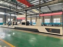
II. Overview of Overall Layout and Main Component Structure:
This machine tool consists of main components including the bed, headstock, workpiece clamping device, workpiece steady rest, oil feeder, boring bar box, boring bar support, feeding system, cooling system, CNC system, and servo tool expansion system.
The machine adopts an overall layout with a movable headstock using servo pressing and a fixed oil feeder, effectively solving the problem of mismatched lengths between the boring bar and workpiece when using ball screws for transmission in deep hole machines. This machine's headstock uses a trapezoidal screw pair for transmission, and its bed guideways use a hard rail structure; the drill rod box uses a ball screw pair for transmission, and its bed guideways use a linear guideway structure.
Note: The image above is not the machine described in this proposal, but the overall layout is generally similar to the machine described herein, for reference only!
1. Bed:
The two guideways of the machine bed are rectangular guideways, quenched for high wear resistance. The bed uses a split structure, assembled together with high-strength bolts and positioned with taper pins.
A high-precision ball screw pair is installed at the right end inside the bed for moving the boring bar box (Z1 axis). The ball screw pair used for the machine's feed (Z1 axis) offers advantages such as smooth transmission, high transmission efficiency, and high precision, and can effectively increase tool life. A trapezoidal screw pair, driven by a servo motor, is installed at the left end inside the bed for moving the headstock (Z2 axis) and pressing the workpiece.
The outside of the guideways is equipped with covers offering excellent leak protection.
2. Headstock:
The headstock is located at the left end of the bed, used to drive the workpiece rotation, and possesses C-axis indexing functionality. The headstock of this machine is driven by a main motor through belts, etc., to rotate the spindle, achieving stepless adjustment to meet various aperture machining requirements. A chuck or taper disc can be installed on the headstock spindle end for workpiece clamping or pressing.
The headstock spindle has a mechanical locking function to meet the requirement of the workpiece not rotating during machining. When mechanically locked, there is an interlock control in the electrical system, preventing the headstock main motor from rotating.
The headstock can move longitudinally along the bed (Z2 axis). Z2 axis movement is accomplished by a trapezoidal screw pair installed at the middle left end of the bed to adapt to the servo pressing of workpieces of different lengths. After the headstock moves into position, it is hydraulically locked to increase workpiece clamping rigidity.
3. Workpiece Steady Rest:
The workpiece steady rest is used for auxiliary support of the workpiece, facilitating workpiece clamping. Its working position should be slightly lower than the position after the workpiece is clamped. By rotating the handwheel to drive the reduction mechanism, the rest moves up and down to adapt to the support requirements of workpieces with different outer diameters. Because the workpiece steady rest is equipped with a reduction mechanism, operating this device is relatively lightweight.
4. Servo Clamping Device:
The servo clamping device is used for clamping the workpiece. It utilizes a servo motor and precision planetary reducer to drive the clamping device through a bidirectional trapezoidal screw to clamp the workpiece. The servo clamping device has self-centering action. Servo clamping features easily adjustable movement speed and clamping force.
5. Oil Feeder:
The oil feeder is fixed on the bed. The oil feeder is a core component of deep hole machine tools, commonly used for tool guidance, cutting oil supply, boring bar support, and workpiece positioning. At the head of the oil feeder, there is a taper disc for positioning and pressing the workpiece. It engages with the workpiece at a 60° taper angle, customized according to workpiece needs. The oil feeder is movable to adapt to the machining of workpieces of different lengths.
6. Boring Bar Box:
The boring bar box is fixed on the feed slide, used to drive the tool rotation and feed. The boring bar box of this machine uses a motor to drive the spindle rotation through belts, etc. The front end of the spindle is equipped with a boring bar holding sleeve for holding the boring bar.
The boring bar box spindle has a mechanical locking function to meet the requirement of the tool not rotating during machining. When mechanically locked, there is an interlock control in the electrical system, preventing the boring bar box main motor from rotating.
7. Boring Bar Support:
Used to support the boring bar. It is equipped with support sleeves that can absorb impacts, vibrations, etc., generated during machining. The boring bar support uses a hook-type design. When the boring bar box retracts, it pulls the boring bar support along with it. When the boring bar support moves to the set position, it automatically disengages from the hook.
8. Servo Tool Expansion System:
The servo tool expansion system, as a machine function expansion module, can achieve two-axis linkage between its tool expansion/contraction movement and the machine's Z1 axis. It can machine high-precision grooves, arcs, curved surfaces, and tapers in deep holes, thereby obtaining complex internal hole cavity profiles.
Due to its complex internal structure, the servo tool expansion system has limitations on the minimum machinable hole diameter and expansion/contraction range. The minimum machinable hole diameter is Φ40mm, and the expansion range is approximately 20mm in diameter. When using the servo tool expansion system, the machining method is: workpiece rotating, tool shank not rotating, oil supplied by the oil feeder, chips removed forward through the already machined hole of the part.
When installing the servo tool expansion system, it needs to pass through the inner hole of the boring bar box spindle, so parts related to BTA drilling need to be removed.
9. Cooling System:
The main function of the cooling system is to use circulating liquid medium to lubricate and cool the cutting area, while removing chips. The cooling system uses an above-ground tank structure. After iron chips in the coolant are removed by the chip conveyor, they undergo three stages of filtration: screen (coarse filtration) -> magnetic filtration -> filter unit fine filtration. The final filtration precision can reach 50μm.
Coolant circulation method: The finely filtered coolant is input from the oil feeder to the cutting area, flows through the inner hole of the workpiece to the chip hopper and magnetic filtration system, then enters the auxiliary tank. A circulation pump then delivers the coolant to the filter unit for purification before entering the clean oil tank, and so on in a cycle.
The cooling system consists of motor pumps forming the oil supply system, providing the required flow rate based on machining needs.
The cooling system is equipped with pressure, flow, level, temperature sensors and display instruments installed on the control panel for easy observation.
10. Grating Scale System:
To improve the two-axis linkage accuracy between the Z1 axis and the servo tool expansion system, a grating scale is installed on the machine's Z1 axis.
11. Control System:
Independent electrical cabinet with good dustproof effect. The cabinet is equipped with a cooling system, allowing electrical components to work in a suitable temperature environment, thereby improving component lifespan and ensuring control system stability and reliability. The CNC system is an 828D.
12. Machine Tool Machining Accuracy Indicators:
C-axis indexing accuracy: 0.5 degrees.
BTA Drilling:
Deviation: Workpiece rotating 0.5mm/1000mm (length-to-diameter ratio not exceeding 100:1).
Hole diameter accuracy: IT8~IT11; Roughness: Ra3.2~6.3μm.
Fine Boring:
Hole diameter accuracy: IT8~IT9; Roughness: Ra1.6~3.2μm.
13. Typical Part Machining Process:
BTA Drilling -> Boring -> Honing -> Grooving (Servo Tool Expansion)
Tool specifications need to be determined based on the part being machined. Except for the honing process, all other processes can be completed on this machine.
14. Machine Tool Working Conditions:
14.1 Power Supply: Three-phase five-wire system power supply, 380V±5%, 50Hz±1Hz.
14.2 Operating Ambient Temperature: 0℃~40℃ (non-freezing).
14.3 Ambient Humidity: Below 80% (non-condensing).
14.4 Altitude: 0~2000m.
14.5 Installation Site Requirements:
Should avoid external vibration influence; Should avoid corrosive gas or liquid influence; Should avoid direct sunlight on the machine surface; Should be away from direct sources of strong cold or hot air; Should minimize dust (metal powder, sand, etc.) pollution.
15. Machine Tool Installation and Debugging Conditions (User Preparation):
15.1 Foundation Requirements: User prepares foundation according to foundation drawing.
15.2 Secondary Grouting: User prepares secondary grouting material and tools.
15.3 Incoming Power Line: Three-phase five-wire system power supply, 380V±5%, 50Hz±1Hz, user provides cable from workshop power source to electrical cabinet.
15.4 Cleaning Oil and Container: Provide 20 liters of gasoline or kerosene, and several cotton cloths.
15.5 Cutting Oil: Deep hole extreme pressure cutting oil, kinematic viscosity at 40°C: 20-25mm²/s, extreme pressure agent content ≥15%, flash point °C ≥160, quantity approx. 5000 liters.
15.6 User prepares lifting slings and tools.
15.7 Tools, accessories, fixtures for machine trial operation (if not ordered by user).
15.8 Lubrication Station: ISO-L-HM32, 30 liters.
16. Machine Tool Installation and Debugging:
16.1 Party B is responsible for providing the machine foundation drawing and general arrangement drawing. Party A should complete the entire foundation construction according to the foundation drawing and general arrangement drawing provided by Party B.
16.2 Before the machine tool arrives at the destination, Party A should complete the first foundation pouring (machine installation foundation), sufficient foundation pre-loading, foundation curing, and prepare for secondary grouting (machine fixing).
16.3 After the machine tool arrives at the destination, Party A is responsible for product hoisting, unloading, and storage (avoiding loss and rain erosion, etc.).
16.4 Upon receiving Party A's installation and debugging notice, Party B will arrange personnel for machine installation and debugging. After Party B's installation personnel complete positioning and preliminary leveling adjustment, they will notify Party A to perform secondary grouting of the installation foundation; after the foundation curing period, proceed to the installation and debugging process.
16.5 Machine installation and debugging work will be carried out by Party B sending professionals in machinery, electricity, inspection, etc., to Party A's site. Party A should assign relevant personnel to assist during installation and debugging and provide necessary working conditions.
16.6 Party A needs to prepare the power supply, lifting equipment, auxiliary materials, oils, and necessary tools and measuring instruments during the installation and debugging process.
17. Machine Tool Acceptance:
Machine tool acceptance is divided into two stages: Pre-acceptance and Final acceptance. Pre-acceptance is conducted at Party B's factory, Final acceptance is conducted at Party A's usage site.
17.1 After the machine tool is assembled and debugged at Party B's assembly site, Party B will notify Party A. Party A should promptly send relevant personnel to Party B's assembly site for pre-acceptance work, machining 1 test piece. The pre-acceptance standard is based on the technical proposal or agreement signed by both parties.
If Party A cannot provide the test piece, tools, or accessories, Party B's standard test piece, tools, and accessories will be used for pre-acceptance trial machining.
After pre-acceptance is completed, both parties sign the pre-acceptance minutes.
17.2 Final acceptance refers to the final acceptance work after the machine tool is installed and debugged at Party A's usage site. Machine 1 test piece. The test piece, tools, and accessories are provided by Party A. The final acceptance standard is based on the technical proposal or agreement signed by both parties; meeting the requirements is considered passing final acceptance, and both parties sign the final acceptance certificate. The machine warranty period starts from the date of signing the final acceptance certificate by both parties. If there are still pending matters during the final acceptance process, they can be written into the final acceptance memorandum for negotiation and handling by both parties.
17.3 Only machines with a signed final acceptance certificate are entitled to usage rights by Party A, and Party B provides warranty, technical support, and other follow-up services.
18. After-Sales Service:
18.1 Training: Party B provides 3 working days of training for Party A's programming, operation, and maintenance personnel. During the training period, Party B is responsible for guiding Party A's relevant technical and operational personnel in trial production of typical parts.
18.2 Party B strictly complies with the company's product after-sales service commitment.
19. Random Technical Documentation:
Mechanical Manual: 1 set
Electrical Manual: 1 set
PLC Program Backup Disk: 1 set
Machine General Arrangement Drawing and Foundation Drawing: 1 set
Machine Packing List: 1 set
Certificate of Conformity: 1 set
20. Machine Tool Manufacturing and Inspection Standards:
Standard: GB/T 9061-2006 / Item: Metal-cutting machine tools - General technical specifications
Standard: GB/T 5226.1-2019 / Item: Safety of machinery - Electrical equipment of machines - Part 1: General requirements
Standard: GB/T 25373-2010 / Item: Metal-cutting machine tools - General technical specifications for assembly
Standard: JB/T 6088.1-2006 / Item: Deep hole drilling and boring machines - Part 1: Testing of the accuracy
Standard: JB/T 6088.2-2006 / Item: Deep hole drilling and boring machines - Part 2: Technical conditions
21. Matters not covered herein shall be negotiated by both parties.
Table 1: Main Technical Parameters of the Machine Tool
| Item | Main Parameters | Remarks |
|---|---|---|
| Machining Range | Machinable Hole Diameter Range | Φ30~Φ200mm |
| Max. Machining Depth | 5000mm | |
| Workpiece Outer Diameter Range | Φ60mm~Φ300mm | |
| Workpiece Length Range | 500mm~5000mm | |
| Machine Performance | Z1 Axis (Boring Bar Box Feed) | Feed Speed Range: 1~7000mm/min |
| Servo Motor Rated Torque/Power: 50Nm/10.5kW | ||
| Rated Traction Force: ≥78kN | ||
| Z2 Axis (Headstock Movement) | Rapid Traverse Speed: 2000mm/min | |
| Servo Motor Rated Torque/Power: 30Nm/5.2kW | ||
| Servo Clamping Device | Rapid Traverse Speed: 3000mm/min | |
| Servo Motor Rated Power: 1.5kW | ||
| Headstock | Speed Range: 20~200r/min (Stepless调速) | |
| Motor Rated Power: ≥30kW (Total) (Servo Spindle Motor) | ||
| Boring Bar Box | Speed Range: 40~1200r/min (Two-range stepless) | |
| Motor Rated Power: 45kW | ||
| Other | Machine Total Rated Power: Approx. 135kW | |
| Machine Load Capacity: 3 Tons | ||
| Cooling System | Cooling Pump Motor | 18.5kW (Two units) |
| Circulation Pump Motor | 2.2kW (Two units) | |
| Max. Pressure | 2.5bar | |
| Flow Adjustment Range | 300~600L/min (Constant flow speed control) | |
| Filtration Precision | 50μm | |
| Tank Max. Volume | Approx. 8000L | |
| Hydraulic System | Max. Pressure | 100bar |
Table 2: Main Configuration List of the Machine Tool
| No. | Name | Model/Specification | Brand | Remarks |
|---|---|---|---|---|
| 1 | CNC System | 828D | Siemens | |
| 2 | Z1 Axis Servo Motor | 50Nm/10.5kW | Siemens | Feed System |
| 3 | Z2 Axis Servo Motor | 30Nm/5.2kW | Siemens | Headstock Movement |
| 4 | Grating Scale | Heidenhain | Z1 Axis, 1 set | |
| 5 | Headstock Main Motor | ≥30kW (Total) | Siemens | Servo Spindle Motor |
| 6 | Boring Bar Box Main Motor | 45kW | MK | Servo Spindle Motor |
| 7 | Spindle Bearings | HRB, ZWZ, ZYS | ||
| 8 | Ball Screw Pair | Nominal OD Φ80 | Hiwin or equivalent | Z1 Axis |
| 9 | Trapezoidal Screw Pair | Nominal OD Φ80 | Self-made | Z2 Axis |
| 10 | Linear Guideways | RG65 | Hiwin or equivalent | |
| 11 | Precision Planetary Reducer | Faston (Taiwan) | Taiwan | |
| 12 | Spindle Encoder | Domestic Quality Brand | ||
| 13 | Three-Jaw Self-Centering Chuck | K11-400 | Domestic Quality Brand | |
| 14 | Cooling System Pumps | Domestic Quality Brand | ||
| 15 | Filter | Filtration Precision 50μm | Domestic Quality Brand | |
| 16 | Main Hydraulic Components | Domestic Quality Brand | ||
| 17 | Main Electrical Components | Quality Brand |
Table 3: List of Machine Tool Component Quantities
| No. | Name | Unit | Qty | Remarks |
|---|---|---|---|---|
| 1 | Bed | Set | 1 | |
| 2 | Headstock | Set | 1 | |
| 3 | Workpiece Clamping Device | Set | 2 | Servo Clamping |
| 4 | Workpiece Steady Rest | Set | 2 | |
| 5 | Oil Feeder | Set | 1 | |
| 6 | Boring Bar Support | Set | 3 | |
| 7 | Boring Bar Box | Set | 1 | |
| 8 | Cooling System | Set | 1 | |
| 9 | Lubrication System | Set | 1 | |
| 10 | Hydraulic System | Set | 1 | |
| 11 | CNC System | Set | 1 | |
| 12 | Chip Removal Device | Set | 1 |
Table 4: Optional Additional Components for the Machine Tool
| No. | Name | Model/Specification | Brand | Qty | Remarks |
|---|---|---|---|---|---|
| 1 | Oil Mist Separator | 1 | |||
| 2 | Oil Cooler | YB180 | 1 |
Hot Tags: cnc deep hole drilling and boring machine for military industry, China, suppliers, manufacturers, factory, customized, price, cheap, company, cost, for sale
You Might Also Like


