Latest Products

Contact Us
Add: No.21, D Zone Jingjinluji Industry Park, Xingfu Road, Dezhou City, Shandong, China
Whatsapp/Wechat: +8615165964868
SKYPE: susanleeguobin
Email: dzguanlu@dzguanlu.com
Official webiste: www.dzgljc.com

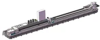
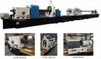
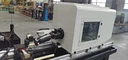
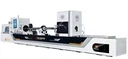
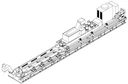
Deep Hole Drilling Machine For Hole 20mm To 100mm
1. Machine Brief: 1.1 Machine processing range: Solid drilling diameter range :Φ20-Φ120mm Outer diameter range :Φ100-Φ400mm Weight of workpiece: 700KGS-10000KGS Length of workpiece: 2000mm-6500mm Drilling depth:2500mm 1.2 Machine functions: Drilling (BTA Drilling Method): Cutting...
Description
mahine tool processing methods: workpiece rotation, tool rotation, tool feed.


2. Machine main parameters:
|
Specification |
Parameters |
Note |
||
|
Working capacity |
Drilling diameter range |
Φ20~Φ120mm |
||
|
Outer diameter range |
Φ 100~Φ400mm |
|||
|
Length of workpiece |
2000-6500mm |
|||
|
Max. machining depth |
2500mm |
|||
|
Machine performance |
Z1 axis(drill box feeding) |
Infeed speed range |
5~1000mm/min |
|
|
Rapid traverse rate |
2000mm/min |
|||
|
Max. Feeding force |
60KN |
|||
|
Servo motor/torque |
19Nm/3KW |
|||
|
X axis(Oil feeder movement) |
Rapid traverse rate |
2000mm/min |
Stepless |
|
|
Max. Feeding force |
60KN |
|||
|
Servo motor/torque |
19Nm/3KW |
|||
|
Drill box |
Rotary speed range |
30-1000r/min |
||
|
Gear |
Manual 3-speed ranges with stepless regulation within each range |
|||
|
Motor |
37KW |
Servo spindle motor |
||
|
Headstock |
Rotary speed range |
30-500r/min |
||
|
Motor power |
37KW |
Servo spindle motor |
||
|
Gear |
Manual 3-speed ranges with stepless regulation within each range |
|||
|
Chuck |
Φ400mm |
Manual 3- jaw chuck |
||
|
Spindle Taper Hole |
Metric 140 |
|||
|
Machine total power |
120kw |
|||
|
Machine load bearing |
10T |
|||
|
Machine footprint |
16mx3.3m |
|||
|
Total machine weight |
20T |
|||
|
Center rest clamping range |
Φ100~Φ400mm |
|||
|
Width of machine bed |
600mm |
|||
|
Center height(from flat guideway to spindle center) |
400mm |
|||
|
Cooling system |
Max.pressure |
2.5MPa |
||
|
Max. flow |
400L/min |
|||
|
Oil tank capacity |
5300L |
|||
3. Machine Main Components Manufacturer List:
|
Name |
Manufacturer |
|
PLC control system |
DELTA |
|
Servo motor for X-axis |
Chinese |
|
Servo motor for Z-axis |
Chinese |
|
Main motor for headstock |
MK |
|
Main motor for drill box |
MK |
|
Coolant pump motor |
Chinese |
|
Main electric components |
Siemens or Schneider |
|
Spindle bearing for drill box |
Haval Bearing |
|
Spindle bearing for headstock |
Haval Bearing |
|
Coolant pump |
Chinese |
|
Rack |
YYC Taiwan |
|
Chuck for headstock |
Chinese |
4. Machine accuracy:
Skewness:0.4mm/1000mm
Drilling: Hole accuracy: IT9-11
Surface roughness: Ra6.3-12.5um
5. Machine tool protection measures:
l Machine tool lubrication oil shortage protection
l Liquid level and pressure protection for the cooling system
l Overload protection for the spindle box motor
l Feed motor load protection
l Cooling pump motor fault alarm
l Alarm for lubrication motor failure of headstock box or drill pipe box
l Limit protection
6. Machine standard parts:
|
NO |
ITEM |
QTY |
|
1 |
PLC control system |
1set |
|
2 |
Machine bed |
1set |
|
3 |
Drill box |
1set |
|
4 |
Headstock |
1set |
|
5 |
3-jaw chuck for headstoxk |
1set |
|
6 |
Workpiece support rest |
2sets |
|
7 |
Oil pressure head |
1set |
|
8 |
Coolant system |
1set |
|
9 |
Feeding carriage |
1set |
|
10 |
Lubrication system |
1set |
|
11 |
Electric box (with air conditioning) |
1set |
|
12 |
Manual |
1set |
|
13 |
Boring bar support rest |
2sets |
|
14 |
Closed type center rest |
2sets |
7. Random information:
Foundation and installation plan, general drawing of machine, operation manual, Control and program manual, electrical description.
8. Working conditions of machine tools:
8.1 Power Supply: Three-phase five-wire power supply, 380V± 5%, 50Hz±1 Hz.
8.2 Working environment temperature: 0℃ to 40℃. (Does not freeze
8.3 Ambient humidity below 80% (no condensation)
8.4 Altitude: 0-2000 meters
9. Machine tool installation and commissioning conditions (prepared by the user)
9.1 Foundation Requirements: The user shall prepare the foundation according to the foundation drawing
9.2 Secondary Irrigation: The user prepares the secondary irrigation grouting material and tools
9.3 Incoming power supply: Three-phase five-wire power supply, 380V± 5%, 50Hz±1 Hz. The user provides the cable from the workshop power supply to the electrical cabinet
9.4 Cleaning oil and utensils: Provide 20 liters of gasoline or kerosene and several cotton cloths
9.5 Cutting Oil: Deep hole extreme pressure cutting oil, kinematic viscosity at 40℃ : 20-25mm2/s, extreme pressure agent content ≥15%, flash point at ℃≥160, usage approximately 5300 liters.
9.6 The user prepares the lifting gear and tools for hoisting
9.7 Cutting tools, accessories and fixtures for machine tool test runs (if the user has not placed an order).
9.8 Lubrication Station: ISO-L-HM32, 100 liters
Hot Tags: deep hole drilling machine for hole 20mm to 100mm, China, suppliers, manufacturers, factory, customized, price, cheap, company, cost, for sale
You Might Also Like