
Latest Products


Contact Us
Add: No.21, D Zone Jingjinluji Industry Park, Xingfu Road, Dezhou City, Shandong, China
Whatsapp/Wechat: +8615165964868
SKYPE: susanleeguobin
Email: dzguanlu@dzguanlu.com
Official webiste: www.dzgljc.com

TSK2130A X3m CNC Deep Hole Drilling And Boring Machine
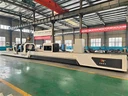
Machine tool appearance diagram For reference only, the actual product shall prevail Machine Tool Overview 2.1 Machine tool processing scope Drilling range: Φ40 ~ Φ155mm Boring range: Φ40 ~ Φ300mm Workpiece outer diameter range: Φ60 ~ Φ400mm 2.2 Machine tool functions...
Description
Machine tool appearance diagram


For reference only, the actual product shall prevail
Machine Tool Overview
2.1 Machine tool processing scope
Drilling range: Φ40 ~ Φ155mm
Boring range: Φ40 ~ Φ300mm
Workpiece outer diameter range: Φ60 ~ Φ400mm
2.2 Machine tool functions
Machine tool processing mode: workpiece rotates, tool does not rotate, tool feeds; Workpiece rotation, tool rotation, tool feed.
Drilling: BTA drilling method, cutting oil is supplied into the tool through the gap between the oil pressure head , the tool bar and the hole wall, and discharged through the inner hole of the tool bar with chips.
Boring: Cutting oil is fed into the tool through the gap between the oil Pressure head, tool bar and hole wall, and is discharged through the bottom hole of the workpiece with chips. During machining, the tool moves close to the Headstock.
2.3 Main structure of machine tool
2.3. 1 Main components of machine tools
Bed body, Headstock, oil pressure head, tool bar bracket, drillling box, sliding guide rail, gear rack and pinion, cooling system, control system, electric box, workpiece bracket, etc.
2.3. 2 Workpiece clamping
The manual three-jaw chuck on the headstock clamps one end of the workpiece, and the oil pressure head cone plate automatically tightens the other end of the workpiece.

Workpiece clamping diagram
2.3. 3 Machine tool control system
Control system PLC
Z-axis: the longitudinal feed motion of the drilling box, and the servo motor drives the rack and pinion mechanism through the reduction mechanism.
X axis: The oil pressure head servo tightens the workpiece, and the servo motor drives the rack and pinion mechanism through the reduction mechanism.
An industrial screen is installed on the machine tool, and the operator can operate and monitor the machine tool in real time on the industrial screen.
It can set the rotating speed, feed rate, processing depth, and can be adjusted steplessly during processing, especially suitable for difficult-to-machine materials such as titanium alloy, stainless steel and high-temperature alloy.
At the same time, it has a variety of monitoring and alarm displays, which can digitally display the flow, pressure, liquid level and oil temperature of the cooling system.
The operation interface is simple and easy to understand, easy to use and convenient to operate.
Control station renderings
2.3. 4 The basic parts such as the box, bed, and pallet are precision cast of high-quality cast iron. After the casting is completed, they undergo two aging treatments to eliminate internal stress, stabilize the structure and size, and improve mechanical properties.
2.3. 5 Bed
The bed body is cast with resin sand, and after casting, it is normalized. The bed adopts a split structure, which is assembled together by high-strength bolts and positioned by taper pins.
Adopt double rectangular sliding guide rail, precision grinding, guide rail surface quenching hardness is high.
The bed is equipped with a helical rack for cutter feed transmission, and the rack is precisely machined and quenched. The machine tool has large load capacity, sufficient rigidity and stable transmission.
V-shaped inclined bars are arranged inside the bed body, which has high support strength and is not easy to deform; The outer wall of the bed directly supports the guide rail, which can bear large cutting force. The rigidity of the guide rail is good, and it is not easy to deform and shake during processing, which is conducive to improving the machining quality and efficiency of the machine tool.
An oil return groove is cast around the bed body, an oil retaining cover is installed on the oil return groove, and the cutting oil on the bed body is automatically returned to the cooling oil tank.
2.3. 6 Headstock
Is used to drive the workpiece to rotate and is fixed at the left end of the bed body.
Manual 3 gears, stepless speed regulation in gears, servo spindle motor drives the spindle to rotate through belt and gearbox, and a manual three-jaw chuck is assembled at the front end of the bedside box for clamping workpieces.
Gears are precision grinded; The tooth surface of the gear is quenched by high frequency, so that the gear can obtain high strength, high hardness, high wear resistance and high fatigue limit, and can withstand relatively large alternating load and impact load.
The external lubricating oil tank is used for cyclic lubrication of gears and bearings, and a low liquid level alarm device is installed in the oil tank.
A button plate is installed on the Headstock, which has the functions of spindle inching, feeding forward, feeding backward and emergency stop.

Sketch diagram of headstock appearance
2.3. 7 Oil pressure head
Used for tool guidance, tool oil supply, tool bar support.
The servo motor is used to drive its axial movement, which can adapt to the processing of workpieces of different lengths, and tighten and loosen the workpieces. The servo motor can be operated in torque mode or position mode.
The oil pressure head slewing bearing is installed inside the oil pressure head body, which has good rigidity and high slewing accuracy.
The rotary seal is installed on the outside of the right end of the oil pressure head body, which is convenient for maintenance.
Install the tool bar support sleeve at the right end of the oil pressure head, which is used to support the tool bar.
The left end of the oil pressure head is equipped with a guide sleeve, a conical disc and an oil retaining device, the conical disc is used for positioning the workpiece, and the guide sleeve is used for guiding the tool.
The oil retaining device is a push-pull structure, and an oil receiving box is installed at the lower part of the oil retaining device, so that the cutting oil flows back to the oil tank.


Appearance diagram of oil pressure head
2.3. 8 Drill pipe box
Used to drive the cutter rotating, mounted on the feed pallet.
Manual 3rd gear, stepless speed regulation in gear, servo spindle motor drives the spindle to rotate through belt, pulley and gear train.
The left end of the spindle is equipped with a tool holder connecting sleeve for holding the tool.
A chip discharge bucket is installed at the right end of the spindle for discharging chips.
Gears are precision grinded; The tooth surface of the gear is quenched by high frequency, so that the gear can obtain high strength, high hardness, high wear resistance and high fatigue limit, and can withstand relatively large alternating load and impact load.
The external lubricating oil tank is used for cyclic lubrication of gears and bearings, and a low liquid level alarm device is installed in the oil tank.

Appearance diagram of drill pipe box
2.3. 9 Tool bar holder
For supporting the knife bar;
It adopts a high-rigidity integral structure, and is equipped with a support sleeve, which can absorb the impact, jitter, etc. generated during processing.
The automatic hanging and pulling mechanism is installed. When the tool is withdrawn, the feed pallet can automatically pull the tool bar bracket back to the initial position.
Appearance diagram of tool bar holder
2.3. 10 Cooling System:
It is mainly composed of cooling pump, chip receiving box, oil tank, etc. to provide enough cutting oil for deep hole machining.
On-ground fuel tank, the fuel tank is fully welded with high-quality steel plate.
Install a telescopic protective cover between the chip boxes on the fuel tank to cover the fuel tank and prevent sundries from falling into the fuel tank.
The pressure, liquid level, oil temperature and flow rate of cutting oil can be digitally displayed on the control station.

Cooling system diagram
2.3. 11 Feed pallet
Used to drive the tool to move axially.
The automatic lubrication station is used to lubricate the sliding guide rail surface regularly and quantitatively.
A button plate is installed on the pallet, which has the functions of inching, feeding forward, feeding backward and emergency stop of the spindle of the drill pipe box.
2.3. 12 Lubrication system
The sliding guide rail surface of the feed pallet is lubricated regularly and quantitatively by the automatic lubrication station, and has the function of low liquid level alarm.
The bearings and gears of the bedside box are lubricated by independent external oil tank circulation and have low liquid level alarm function.
The bearings and gears of the drill pipe box are lubricated by independent external oil tank circulation and have low liquid level alarm function.
The oil feeder support plate and the knife bar support support plate are lubricated by manual lubrication pump.
2.3. 13 Workpiece carrier
Used for workpiece prepositioning.
The operator first places the workpiece on the workpiece bracket, and after the workpiece is clamped and positioned, the workpiece leaves the bracket.
The V-shaped frame on the workpiece carrier is manually raised and lowered by using the T-shaped screw.

Workpiece carrier schematic diagram
2.3. 14 Center frame
For supporting workpieces; Three-point closed central frame structure with two rollers below and one roller above; The two rollers below adjust the lateral position by the lead screw.

Schematic diagram of center frame
Machine tool main parameters
Main configuration list of machine tools
|
Technical specifications |
parameter |
remark |
||
|
Scope of work |
Range of drilling |
Φ40 ~ Φ155mm |
||
|
Push boring range |
Φ40 ~ Φ300mm |
|||
|
Maximum machining depth |
8000mm |
|||
|
Workpiece length range |
500-8000mm |
|||
|
Workpiece outer diameter range |
Φ60 ~ Φ400mm |
|||
|
Machine tool performance |
Z axis (drilling box feed) |
Feed speed range |
5 ~ 1000mm/min |
|
|
Fast moving speed |
2000mm/min |
|||
|
Servo motor torque/power |
27Nm/4.3 KW |
|||
|
Maximum feed force |
60KN |
|||
|
X-axis (Oil pressure head movement) |
Fast moving speed |
2000mm/min |
||
|
Servomotor torque |
27Nm/4.3 KW |
|||
|
Maximum jacking force |
60KN |
|||
|
Drilling box |
Speed range |
30 ~ 500r/min |
||
|
Motor power |
45KW |
Servo spindle motor |
||
|
Gear position |
Manual 3 gears, intra-gear stepless speed regulation |
|||
|
Spindle front taper bore |
Metric 140 |
|||
|
Headstock |
Speed range |
30 ~ 500r/min |
||
|
Motor power |
45KW |
Servo spindle motor |
||
|
Gear position |
Manual 3 gears, intra-gear stepless speed regulation |
|||
|
Chuck outer diameter |
Φ 400mm |
Manual three-claw |
||
|
Spindle front taper bore |
Metric 140 |
|||
|
other |
Total power of machine tool |
127KW |
||
|
Width of guide rail |
690mm |
|||
|
Machine tool load-bearing |
8 tons |
|||
|
Machine tool footprint |
22.5 m × 3.3 m |
|||
|
Height from center of spindle to above guide rail |
400mm |
|||
|
Cooling system |
Maximum pressure |
2.5 MPa |
||
|
Maximum flow rate |
400L/min |
|||
|
Fuel tank volume about |
6500L |
|||
|
Part Name |
Manufacturer |
|
Control system |
Delta |
|
X-axis servo motor |
Wuhan Maixin |
|
Servomotor for Z axis |
Wuhan Maixin |
|
Bedside box main motor |
Sichuan Emke |
|
Drill pipe box main motor |
Sichuan Emke |
|
Motor for cooling pump |
Domestic famous products |
|
Main electrical components |
Schneider or SIEMENS |
|
Spindle bearing for drill pipe box |
Havalo |
|
Spindle bearing for headbox |
Havalo |
|
Cooling pump |
Domestic famous products |
|
Rack |
Taiwan original Yichang or equivalent brand |
|
Chuck for bedside case |
Zhejiang Garden Brand |
Machine tool standard
|
Serial number |
Name |
Quantity |
remark |
|
1 |
Bed body |
1 set |
|
|
2 |
Drill pipe box |
1 set |
|
|
3 |
Bedside box |
1 set |
|
|
4 |
Three-jaw self-centering chuck for bedside box |
1 set |
|
|
5 |
Workpiece carrier |
2 sets |
|
|
6 |
Oil feeder |
1 set |
|
|
7 |
Cooling system |
1 set |
|
|
8 |
Feed pallet |
1 set |
|
|
9 |
Lubrication system |
1 set |
|
|
10 |
Numerical control system |
1 set |
|
|
11 |
Electric box (with air conditioning) |
1 set |
|
|
12 |
Instructions |
1 set |
|
|
13 |
Tool bar holder |
3 sets |
|
|
14 |
Center frame |
2 sets |
Optional
|
Serial number |
Name |
model |
remark |
|
1 |
cutter |
ΦD |
|
|
2 |
Cutter holder |
Φd |
|
|
3 |
Auxiliary device |
Φd |
|
|
4 |
Guide sleeve |
ΦD |
|
|
5 |
Conical disc |
Customized according to the outer diameter of the workpiece |
|
|
6 |
Cutting oil |
Deep hole extreme pressure cutting oil 6500 liters |
|
|
7 |
Chain plate automatic chip removal machine |
Width 500 |
|
|
8 |
Oil cooler for cooling system |
Refrigeration capacity 12KW |
|
|
9 |
Drum paper belt filter for cooling system |
Filtration accuracy 50 μm |
Machining accuracy
7.1 Rough boring and drilling:
Aperture accuracy IT9 ~ 11
Surface roughness: Ra6.3 to Ra12.5 μm.
Skewness: 0.5 mm/1000mm
7.2 Fine boring:
Aperture accuracy IT8 ~ 9
Surface roughness: Ra1.6-3.2 μm.
8. Machine tool protection measures
Machine tool lubrication oil deficiency protection
Cooling system level and pressure protection
Headstock Motor Overload Protection
Feed motor load protection
Cooling pump motor fault alarm
Fault alarm of lubrication motor in bedside box or drill pipe box
Limit protection
9. Random technical data
|
Machinery Instructions |
1 set |
|
Electrical instructions |
1 set |
|
PLC program backup disk |
1 set |
|
Appearance and foundation drawings of machine tools |
1 set |
|
Machine tool packing list |
1 set |
|
Certificate of Conformity |
1 set |
10. Machine tool manufacturing and inspection standards
|
Criteria |
Items |
|
GB/T 9061-2006 |
General specifications for metal cutting machine tools |
|
GB/T 5226.1-2019 |
Electrical safety of machinery-Electrical equipment of machinery-Part 1: General specifications |
|
GB/T 25373-2010 |
General specifications for assembly of metal cutting machine tools |
|
JB/T 6088.1-2006 |
Deep-hole drilling and boring machines-part 1: accuracy testing |
|
JB/T 6088.2-2006 |
Deep hole drilling and boring machines-part 2: specifications |
11. Machine tool working conditions
11.1 Power supply: Three-phase five-wire power supply, 380V ± 5%, 50Hz ± 1 Hz.
11.2 Working environment temperature: 0 ℃ ~ 40 ℃. (Non-icing)
11.3 Ambient humidity is less than 80% (no condensation)
11.4 Altitude: 0 ~ 2000m
11.5 Conditions required for installation site:
Should be avoided from external vibration; Avoid being affected by corrosive gases or liquids; Direct sunlight should be avoided on the surface of the machine tool; Should stay away from direct strong cold wind or hot air and other air sources; Dust (metal dust, sand, etc.) pollution should be minimized.
12. Machine tool installation and debugging conditions (user preparation)
12.1 Foundation requirements: The user makes the foundation according to the foundation diagram
12.2 Secondary irrigation: The user prepares grouting materials and tools for secondary irrigation
12.3 Incoming power supply: three-phase five-wire power supply, 380V ± 5%, 50Hz ± 1 Hz, the user provides the cable from the workshop power supply to the electric cabinet
12.4 Cleaning oil and utensils: 20 liters of gasoline or kerosene and some cotton cloth are provided
12.5 Cutting oil: deep hole extreme pressure cutting oil, kinematic viscosity 40 ℃: 20-25 mm ²/s, extreme pressure agent content ≥ 15%, flash point ℃ ≥ 160, dosage approximately 6500 liters.
12.6 User prepares spreaders and tools for hoisting
12.7 Tools, auxiliary devices and fixtures for machine tool commissioning (if the user has not ordered them).
12.9 Lubrication Station: ISO-L-HM32, 100 L
13. Machine tool installation and debugging
13.1 Party B is responsible for providing the foundation drawing and appearance drawing of the machine tool, and Party A shall complete the whole foundation construction according to the foundation drawing and appearance drawing provided by Party B.
13.2 Before the machine tool arrives at the destination of use, Party A shall complete the first irrigation of the foundation (machine tool installation foundation), sufficient foundation preloading and foundation maintenance in advance, and make preparations for the second grouting (machine tool installation and fixation).
13.3 After the machine tool arrives at the destination, Party A is responsible for the hoisting, unloading and storage of the product (to avoid loss and rain erosion, etc.).
13.4 Party B receives the installation and commissioning notice from Party A and arranges personnel to install and adjust the machine tool. After the safety adjustment personnel of Party B have pre-adjusted the machine tool in place and level, they will notify Party A to carry out the secondary grouting of the installation foundation; After the foundation has gone through the maintenance period, it will enter the installation and commissioning process.
13.5 Party B shall send mechanical, electrical, testing and other professionals to Party A's site for machine tool installation and debugging. Party A shall send relevant personnel to assist in the installation and commissioning work and provide necessary working conditions.
13.6 Party A shall prepare power supply, lifting equipment, auxiliary materials, oil and necessary tools and measuring tools during the installation and commissioning process.
14. Acceptance of machine tools
The acceptance of machine tools is divided into two stages: pre-acceptance and final acceptance. The pre-acceptance is carried out at Party B's factory, and the final acceptance is carried out at Party A. 's use site.
14.1 After the assembly and commissioning of the machine tool at Party B's assembly site is completed, Party B shall notify Party A, and Party A shall promptly send relevant personnel to Party B's assembly site for pre-acceptance and process one test piece. The pre-acceptance standard shall be accepted according to the technical scheme or technical agreement signed by Party A and Party B.
If Party A cannot provide test pieces, cutting tools and auxiliary devices, Party B's standard test pieces, cutting tools and auxiliary devices shall be used for pre-acceptance trial processing.
After the pre-acceptance is completed, both parties sign the pre-acceptance minutes.
14.2 The final acceptance of the machine tool refers to the final acceptance of the machine tool after the installation and debugging of Party A. 's use site is completed. Processing one test piece, the test piece, cutting tools and auxiliary devices shall be provided by Party A, and the final acceptance standard shall be accepted according to the technical scheme or technical agreement signed by Party A and Party B; If the requirements are met, the final acceptance shall be deemed to be qualified, and the final acceptance form shall be signed by both parties. The warranty period of machine tool starts from the date of signing the final acceptance form by Party A and Party B. If there are still unfinished matters in the final acceptance process, they can be written into the final acceptance memorandum, which will be handled by Party A and Party B through consultation.
14.3 Party A has the right to use only the machine tools that have signed the final acceptance form, and Party B will provide follow-up services such as warranty and technical support.
15. After-sales service
15.1 Training
Party B shall train Party A's programming, operation and maintenance personnel for a period of 3 working days. During the training period, Party B shall be responsible for guiding Party A's relevant technical and operating personnel to conduct trial production of typical parts.
15.2 Party B strictly abides by Party B's product after-sales service commitment.
16.Machine photos for references only :


17. Global Exhibitions
2023 Beijing Exhibitions


2023 Russia Exhibitions

2023 Hannover in September

2024 shanghai exhibation

2024 year Russia exhibation

2024 year Turkey exhibation

Hot Tags: tsk2130a x3m cnc deep hole drilling and boring machine, China, suppliers, manufacturers, factory, customized, price, cheap, company, cost, for sale
You Might Also Like


