

Latest Products


Contact Us
Add: No.21, D Zone Jingjinluji Industry Park, Xingfu Road, Dezhou City, Shandong, China
Whatsapp/Wechat: +8615165964868
SKYPE: susanleeguobin
Email: dzguanlu@dzguanlu.com
Official webiste: www.dzgljc.com

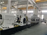
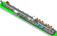
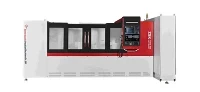
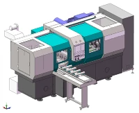
Combined CNC BTA And Gundrilling Machine
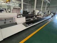
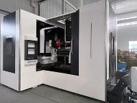
TSK2106F ×2 Com bined CNC BTA Machine and Gundrilling machine Appearance drawing of machine tool Appearance diagram of machine tool 2. Machine Tool Overview 2.1 Processing method: BTA drilling: cutting oil is fed into the tool through the gap between the oil pressure head, the tool bar and...
Description
TSK2106F ×2 Combined CNC BTA Machine and Gundrilling machine
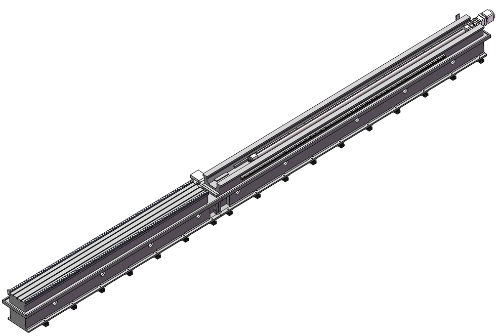
Appearance drawing of machine tool
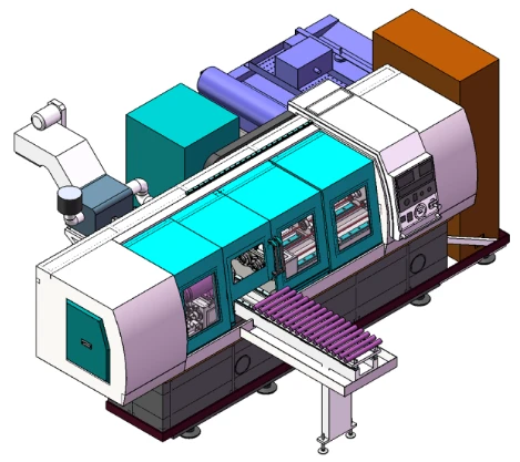
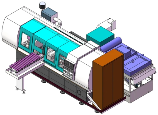
Appearance diagram of machine tool
2. Machine Tool Overview
2.1 Processing method:
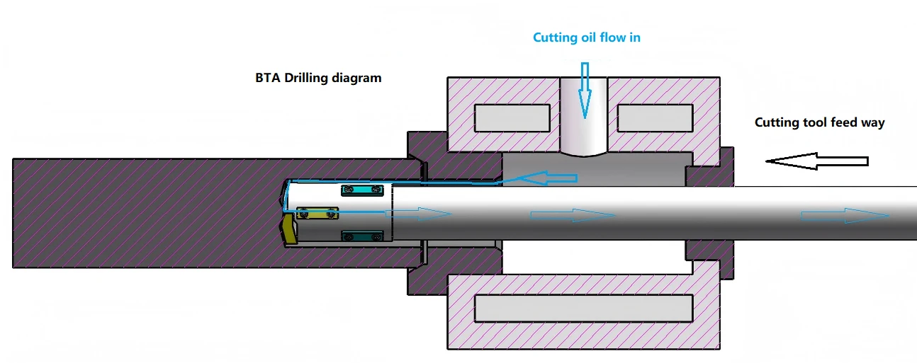
BTA drilling: cutting oil is fed into the tool through the gap between the oil pressure head, the tool bar and the hole wall, and discharged through the inner hole of the drilling bar with chips; The workpiece and tool rotate relative to each other.
Gun drilling mode (external chip discharge): the cutting oil is supplied through the rotary joint at the tail end of the spindle of the drilling box, reaches the cutting part through the inner hole of the tool bar, and is discharged with chips through the gap between the V-shaped groove of the tool bar and the hole wall.
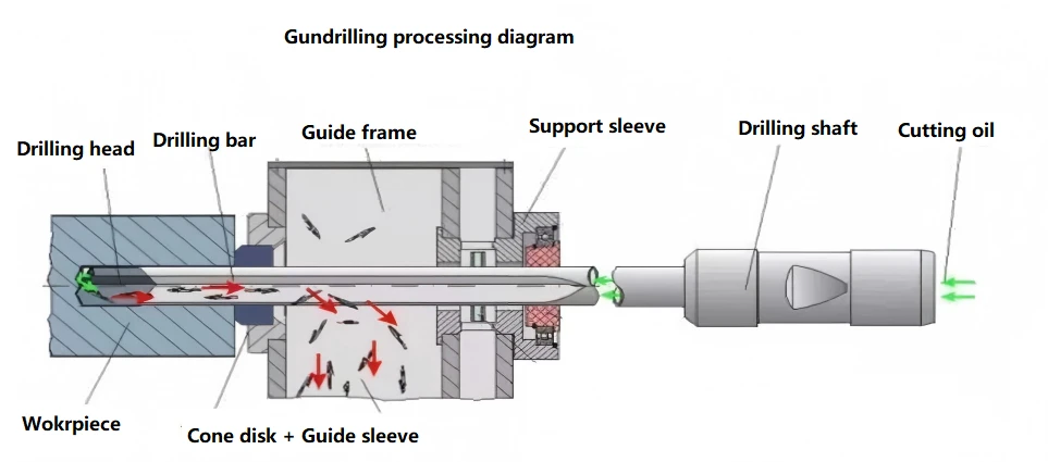
Gun Drill and BTA share a set of spindles. When converting between gun drill and BTA, it is necessary to manually change cutters, auxiliary tools and switch oil path, so that the conversion of the two machining modes can be realized
Machine Tool Working Mode: Workpiece Rotary Tool Rotary and Tool Feed
2.2 Machine Tool Machining Range
Gun drill drilling range: Φ 10-Φ 25mm
BTA drilling range: Φ 25-Φ 60mm
Maximum machining depth: 2000mm
Maximum workpiece length: 2000mm
Number of spindles: 2
Spindle spacing: 200mm
2.3 Main structure of machine tool
2.3.1 Main components of machine tools
Bed body, Headstock, oil pressure head, drilling bar support, Drilling box, cooling system, control system, electric box, workpiece bracket, etc
2.3.2 Workpiece clamping
Cone discs are installed on the headstock and the oil pressure head; The workpiece is placed on the workpiece carrier; The CNC system controls the axial movement of the Headstock; Automatically tighten and position the workpiece by using the chamfer at both ends of the workpiece; After the workpiece is clamped, the workpiece automatically leaves the workpiece bracket; After the machining is completed, the headstock is loosened and the workpiece automatically falls on the workpiece carrier.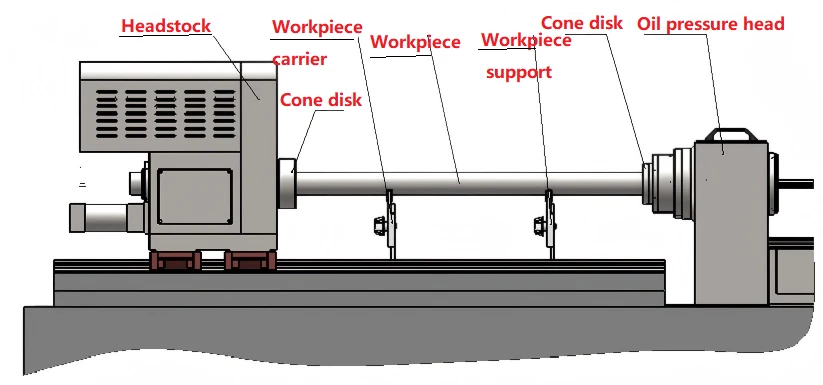
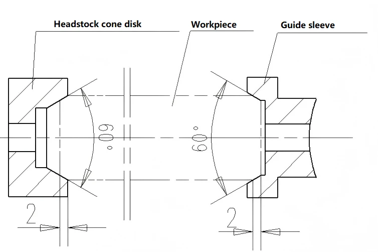
Workpiece clamping diagram
2.3.3 Machine Tool Control System
Control system: SIEMENS-808D
Z-axis: Longitudinal feed motion of drilling box, servo motor drives ball screw mechanism through speed reduction mechanism.
Main control contents: workpiece rotation, tool rotation, tool feed, cooling system, etc.
2.3.4 The foundation parts such as box body, bed body and carriage are precision cast with high-quality cast iron. After casting, they are subjected to two aging treatments to eliminate internal stress, stabilize the structure and size, and improve mechanical properties.
2.3.5 Bed
The bed body is cast with resin sand and normalized after casting. The bed body adopts a split structure, which is assembled together using high-strength bolts and positioned with tapered pins.
Double rectangular sliding guide rail of tool bed, precision grinding, high quenching hardness of guide rail surface; A ball screw is installed in the inner gear of the tool bed body, which is used for tool feeding transmission; A rack is mounted on the side of the tool bed body, which is used to manually adjust the position of the tool bar support.
A ball heavy-duty linear guide rail is installed on the workpiece bed body, and a T-slot worktable is processed. The headstock and center frame can be manually moved on the linear guide rail, which is convenient and quick to move.
V-shaped inclined bars are arranged inside the bed body, which has high support strength and is not easy to deform; The outer wall of the bed body directly supports the guide rail, the guide rail can bear large cutting force, the guide rail has good rigidity, and is not easy to deform and shake in the processing process, which is beneficial to improving the processing quality and efficiency of the machine tool.
An oil return groove is cast around the bed body, an oil retaining cover is installed on the oil return groove, and the cutting oil on the bed body is automatically returned to the cooling oil tank.
2.3.6 Headstock
It is used for driving the rotation of the workpiece and is mounted on the linear guide rail of the workpiece bed.
Double spindle structure, clamping two workpieces at a time; An ordinary motor drives the spindle to rotate through a speed reduction mechanism, and the rotation speed is fixed. The whole headstock is manually moved on the bed body so as to adapt to the change of the length of the workpiece, and after being moved into place, it is manually locked on the bed body; The headstock spindle can be moved axially under the control of the hydraulic system to realize the positioning, clamping/loosening of the workpiece.
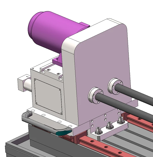
Appearance diagram of heastock
2.3.7 Oil pressure head
Used for cutter guiding, cutter oil supplying, cutter bar supporting and chip removal;
The oil pressure head is installed in the middle part of the bed body.
A tool bar support sleeve is installed at the right end of the oil dispenser, which is used to support the tool bar.
The left end of the oil pressure head is equipped with a guide sleeve and a conical disc. The conical disc is used for positioning the workpiece, and the guide sleeve is used for guiding the tooling.
When the gun drill processing mode, the oil pressure head can remove chips;
In the BTA machining mode, the oil pressure head can supply oil to the tool
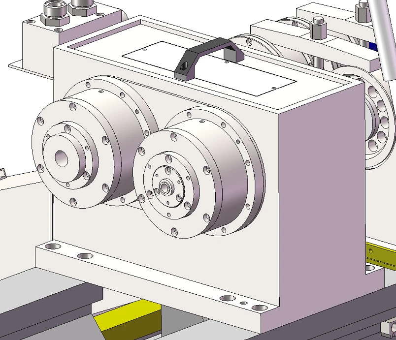
2.3.8 Drilling box
For driving cutting tool rotation, mounted on feed pallet.
The servo spindle motor drives the spindle to rotate through belt and pulley, and the speed is regulated steplessly.
The left end of the spindle is fitted with a tool holder connecting sleeve for clamping the tool.
When BTA is processed, a chip discharge hopper is installed at the right end of the spindle for discharging chips. During gun drilling, a rotary joint is installed at the right end of the spindle to supply oil to the tool.
Double spindle structure, one main motor drives two spindles to rotate.
The main motor front drives the spindle to rotate, and the tail end of the motor is away from the tool holder connecting sleeve, which is beneficial to preventing the motor from entering oil, improving the motor life, and at the same time, it is convenient to change the tool.
A button plate is installed on the box body, which has the functions of spindle jog, forward, backward and emergency stop.
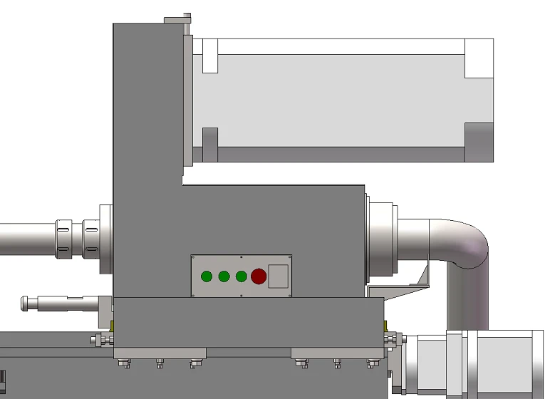
Appearance diagram of drilling box
2.3.9 Drilling bar support
For supporting a tool bar;
It adopts a high rigidity integral structure with a support sleeve on it, which can absorb the impact and jitter generated in the processing process.
Install the automatic hanging and pulling mechanism, when the tool is withdrawn, the feed carriage can automatically pull the tool bar bracket back to the initial position.
At the same time, a manual adjustment gear is installed on the bracket, and the position of the drilling bar bracket on the bed body can also be manually adjusted.
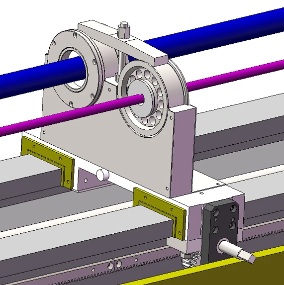
Appearance diagram of drilling bar support
2.3.10 Cooling System:
It is mainly composed of cooling pump, chip conveyor, oil cooler, filter, oil tank, etc., which provides enough cutting oil for deep hole processing.
Above-ground fuel tank, the fuel tank is fully welded with high-quality steel plate.
Chip Conveyor Machine: Remove chips and realize the preliminary separation of oil chips.
Oil cooler: Control the oil temperature within a reasonable range. When the oil temperature is higher than the set upper limit, the oil cooler will start automatically; When the oil temperature is lower than the set lower limit, the oil cooler stops automatically.
Filter: Adopt paper tape filtration, with automatic paper feeding function, improve the cleanliness of cutting oil.
The pressure, level, temperature and flow of cutting oil can be displayed digitally on the control station.
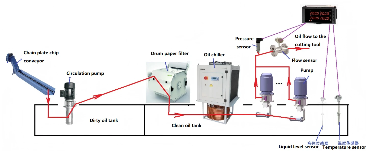
Schematic of cooling system
2.3.11 Lubrication System
The spindle bearings of the bedhead box, the spindle bearings of the drill pipe box and the sliding guide rail surfaces of the feed pallet are lubricated by automatic lubrication station at regular and quantitative times, and have the function of low liquid level alarm.
Others are lubricated with manual lubrication pumps.
2.3.12 Workpiece Carrier
For workpiece pre-positioning.
The operator first places the workpiece on the workpiece bracket, and after the workpiece is clamped and positioned, the workpiece leaves the bracket.
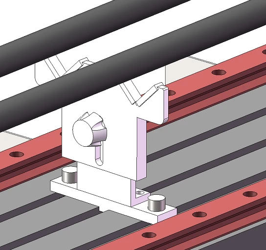
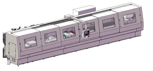
2.3.14 Protection
The diagram of the full protection of the host is as follows:
2.3.15 Feeding Bracket
The workpiece is mounted on a V-shaped feeding bracket. The CNC system controls the servo motor to drive the ball screw to rotate, moving the feeding bracket to the set position.
The feeding bracket adopts rolling linear guides for its movement. Up to 16 workpieces can be placed on the feeding bracket.
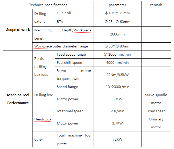
3. Machine parameter :

Contact : Lean Lee
Mob: 008615153489973
Email : export@dzguanlu.com
Hot Tags: combined cnc bta and gundrilling machine, China, suppliers, manufacturers, factory, customized, price, cheap, company, cost, for sale
You Might Also Like


