Latest Products


Contact Us
Add: No.21, D Zone Jingjinluji Industry Park, Xingfu Road, Dezhou City, Shandong, China
Whatsapp/Wechat: +8615165964868
SKYPE: susanleeguobin
Email: dzguanlu@dzguanlu.com
Official webiste: www.dzgljc.com
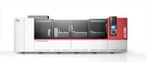
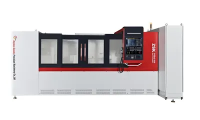
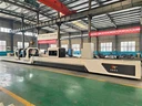
Roller CNC Drilling Machine
Technical Overview: Roller CNC Drilling Machine 1. Machine Introduction and Application This equipment is a Roller CNC drilling machine engineered for high-volume, precision radial hole drilling in large industrial rollers, a critical component in papermaking machinery. Utilizing a twist drill...
Description
Technical Overview: Roller CNC Drilling Machine
1. Machine Introduction and Application
This equipment is a Roller CNC drilling machine engineered for high-volume, precision radial hole drilling in large industrial rollers, a critical component in papermaking machinery. Utilizing a twist drill process, this Roller CNC drilling machine significantly enhances both throughput and, more critically, the positional accuracy and surface finish of each drilled hole.
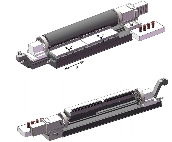
The machine features a horizontal, split-bed design, physically separating the workpiece bed from the tool bed. This configuration minimizes vibration transfer, a key advantage for a Roller CNC drilling machine handling large, heavy components.
It is equipped with 96 drill spindles, organized into two independent feed groups of 48 spindles each. Every spindle is powered by its own AC servo motor, providing individual speed control. The center distance between adjacent spindles is adjustable between 70mm and 75mm, allowing for flexible hole patterns.
The Roller CNC drilling machine is built to handle a variety of demanding materials, including 0Cr17, stainless steel grades 304 and 316, and duplex stainless steels. Feed rates and spindle speeds are adapted based on the specific material to optimize tool life and efficiency.

2. Roller Drilling Process – Step-by-Step Procedure
The operational sequence for this Roller CNC drilling machine follows a systematic approach to ensure accuracy and repeatability across the entire roller surface. The following steps outline the standard production cycle.
Workpiece Setup: The headstock, tailstock, and support idlers are first adjusted to align with the roller's outer diameter, ensuring stable and concentric mounting.
Mounting and Alignment: The roller is secured between the headstock and tailstock. Support idlers provide additional stability, and the tailstock is advanced to firmly clamp the workpiece. Final runout checks are performed to confirm proper alignment.
Tool Zeroing: The tool's coordinate reference point (zero point) is programmed and set within the CNC control, establishing the datum for all subsequent drilling operations on this Roller CNC drilling machine.
Coolant Activation: The high-pressure coolant pump system is engaged to provide adequate lubrication and chip evacuation during the cutting cycle.
Spindle Rotation: The spindle motors for the selected drill group are started, rotating the tools to the preset speed.
First Drilling Cycle (Circumferential): The Z-axis feed is activated, advancing the rotating tools into the workpiece to drill the first group of holes. After this pass, the headstock rotates the roller by a programmed angle, and the Roller CNC drilling machine drills the next group. This indexing sequence repeats until the entire circumference of the current section is completed.
Indexing to Next Section (Axial): Once all holes in a given circumferential section are complete, the tool head moves along the X-axis (the roller's axial direction) by a predetermined pitch. The Roller CNC drilling machine then repeats the circumferential indexing and drilling sequence (Step 6) for this new axial section.
Cycle Completion: The process described in Steps 6 and 7 is repeated iteratively, section by section, until all holes have been drilled across the required axial length of the roller. At this point, the operation on the Roller CNC drilling machine is complete, and the finished part can be unloaded.
Machine Parameters :


Four. Function and Structure of Main Machine Tool Components
The machine tool consists of several major assemblies, including the workpiece bed, tool bed, headstock, tailstock, drilling carriage, drill pipe box, guide frame, feed system, cooling system, electrical control system, and automatic chip removal device. The structure and function of each key component are outlined below.
1. Bed Body
The bed is split into two sections: the workpiece bed and the tool bed. The tool bed incorporates the bed casting, a carriage, an X-axis servo feed mechanism, and a telescopic guideway cover. Around the workpiece bed, broad and deep oil return channels are cast to direct coolant back to the tank efficiently.
The bed is constructed from HT300 grade cast iron, offering good vibration damping, high structural rigidity, and long-term accuracy stability. The guide rails for X-axis movement are medium-frequency hardened and precision-ground. Feed motion along the X-axis is driven by a servo motor through a ballscrew assembly.
2. Headstock
The headstock spindle is powered by a Siemens servo motor coupled with a precision gear reducer, enabling both spindle rotation and indexing. A hydraulically actuated braking mechanism provides strong locking force to prevent workpiece rotation during drilling operations.
Precision bearings support the spindle, and given the relatively low operating speeds, high-grade grease lubrication is used. The headstock can be manually moved transversely along the carriage guide rails to accommodate variations in workpiece diameter. However, axial movement along the workpiece axis is not permitted.
A heavy-duty four-jaw chuck with an outer diameter of 1600 mm is fitted to grip the internal bore of the workpiece.
3. Tailstock
The tailstock supports the workpiece during rotation. It carries a rotatable spindle that can accept a four-jaw chuck similar to that on the headstock, also for internal bore support. Manual locking secures the tailstock in place. Depending on workpiece length, the tailstock can be repositioned axially as needed.
A spindle extension stroke of up to 200 mm allows for positive clamping of the workpiece. Lateral adjustment of the tailstock, accomplished via manual screw operation, permits positioning relative to the workpiece outer diameter.
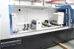
4. Drill Pipe Box – Power Section
The drill pipe box houses up to 96 individually driven spindles, each powered by its own servo motor. Spindle speed is continuously variable, with a maximum of 1500 r/min. Center distances between spindles are adjustable manually within a range of 70–75 mm. High-precision spindle bearings are employed throughout.
The drill pipe box body is made from HT300 cast iron and features a modular design-each spindle is mounted in a separate box, with gaps left between adjacent boxes to minimize thermal deformation and aid heat dissipation.
The base support plate is a single rigid structure, moved axially by a servo motor. Two such pallets are provided, each carrying 48 spindles. Power transmission from motor to spindle is via toothed timing belts of circular arc profile. Automatic continuous lubrication with specialized oil ensures reliable bearing performance.
5. Idler Rollers (Two Sets)
These rollers provide bottom support and lateral positioning for the workpiece. The support diameter is adjustable. The entire roller assembly can be manually shifted transversely to suit different workpiece outer dimensions.
6. Cutting Fluid Cooling and Filtration System
This system primarily comprises a coolant tank, chip conveyor, and pump units.
7. Feed System
Two independent feed axes are provided:
Z-axis: A servo motor drives a ballscrew to move the drill pipe box pallet, enabling infinitely variable feed rates from 5 to 500 mm/min, with a rapid traverse rate of 4 m/min. Linear ball guideways are used.
X-axis: A servo motor, via a reducer, drives a ballscrew to move the carriage transversely along the workpiece axis. Feed rate is continuously adjustable, with rapid traverse at 2 m/min. Twin rectangular slideways are employed.
8. Hydraulic System
This system is dedicated to locking the headstock spindle via hydraulic actuation.
9. Control System
The machine is equipped with a Siemens 828D CNC controller.
Contact us:
Bonnie
Email: info@dzguanlu.com
Whatsapp: +86 15153489983
Hot Tags: roller cnc drilling machine, China, suppliers, manufacturers, factory, customized, price, cheap, company, cost, for sale
You Might Also Like