Latest Products


Contact Us
Add: No.21, D Zone Jingjinluji Industry Park, Xingfu Road, Dezhou City, Shandong, China
Whatsapp/Wechat: +8615165964868
SKYPE: susanleeguobin
Email: dzguanlu@dzguanlu.com
Official webiste: www.dzgljc.com
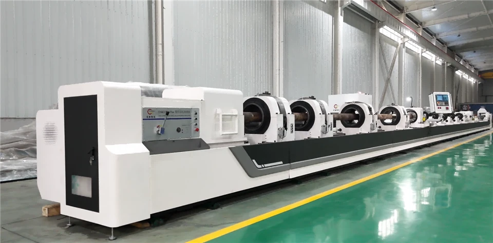
TSK2150×8m CNC Deep Hole Drilling & Boring Machine
Machine Functions Machine operating modes: Workpiece rotation with non‑rotating tool and tool feed; Workpiece rotation together with tool rotation and tool feed. Drilling: Adopt BTA drilling method. Cutting oil is supplied to the tool through the oil feeder and the clearance between the tool bar and hole wall. Chips are carried out through the inner bore of the tool bar. Boring: Cutting oil is supplied to the tool through the oil feeder and the clearance between the tool bar and hole wall. Chips are discharged through the bottom hole of the workpiece. During machining, the tool moves towards the headstock. Trepaning: Internal oil supply and external chip removal. Cutting oil is fed to the tool via the inner bore of the tool bar, and chips are carried out through the gap between the outer wall of the tool bar and the machined hole.
Description
1. Machine Overview
1.1 Machine Machining Range
Drilling range: Φ30~Φ150 mm
Boring range: Φ40~Φ500 mm
Trepaning range: Φ120~Φ400 mm
Max. machining depth: 8 m
Max. workpiece length: 8 m
1.2 Machine Functions
Machine operating modes: Workpiece rotation with non‑rotating tool and tool feed; Workpiece rotation together with tool rotation and tool feed.
Drilling: BTA drilling method is adopted. Cutting oil is supplied to the tool through the oil feeder and the clearance between the tool bar and hole wall, and chips are carried out through the inner bore of the tool bar.
Boring: Cutting oil is supplied to the tool through the oil feeder and the clearance between the tool bar and hole wall, and chips are discharged through the bottom hole of the workpiece. During machining, the tool moves towards the headstock.
Trepaning: Internal oil supply and external chip removal. Cutting oil is fed to the tool via the inner bore of the tool bar, and chips are carried out through the gap between the outer wall of the tool bar and the machined hole.
1.3 Main Purpose and General Layout of the Machine
This machine is specially designed for deep‑hole machining of cylindrical and square workpieces. The machine bed features high rigidity and good precision retention performance, suitable for inner‑hole processing of large‑size workpieces. It has a wide spindle speed range. The feed system is driven by AC servo motors to meet the requirements of various deep‑hole machining processes. The oil feeder presses against the workpiece by servo drive.
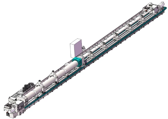
1.3.1 Main Machine Components
Machine bed, headstock, oil feeder, tool bar support, sliding guideways, gear‑rack assembly, cooling system, PLC control system, electrical cabinet, center rest, etc.
1.3.2 Workpiece Clamping
1.3.2.1 For Drilling and Boring Operations
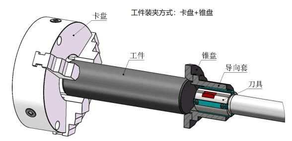
One end of the workpiece is clamped by the chuck mounted on the headstock, and the other end of the workpiece is pressed tightly by the cone disk on the oil feeder.
1.3.2.2 For Trepaning Operations
One end of the workpiece is clamped by the manual three‑jaw chuck on the headstock, and the other end is supported by the center rest.
1.3.3 Machine Control System
Control system: PLC control system Z1 servo axis: Longitudinal feed movement of the drill box. The servo motor drives the gear‑rack mechanism via a reduction unit. Z2 servo axis: Servo‑driven pressing of the workpiece by the oil feeder. The servo motor drives the gear‑rack mechanism via a reduction unit.
1.3.4 Basic components including boxes, machine bed and carriage are precision‑cast from high‑quality cast iron. Two times of aging treatment are carried out after casting to eliminate internal stress, stabilize microstructure and dimensions, and improve mechanical properties.
1.3.5 Machine Bed
The machine bed is resin‑sand cast and normalized after casting. It adopts split‑type structure, assembled together with high‑strength bolts and positioned by taper pins.
Double rectangular sliding guideways are applied with precision grinding, and the guideway surfaces feature high quenching hardness. Dimension of single guideway: width × thickness = 180 mm × 50 mm; total guideway width: 800 mm. A helical rack (module 6) is installed inside the bed for tool feed transmission. The rack is precision‑machined and quenched, delivering high guiding accuracy and good wear resistance. The precision rack is mounted in the middle of bed guideways for feed and rapid traverse of the carriage. The machine features heavy load‑bearing capacity, sufficient rigidity and stable transmission.
V‑shaped inclined ribs are arranged inside the bed for high supporting strength and low deformation tendency. The outer wall of the bed directly supports the guideways, enabling the guideways to withstand heavy cutting forces with high rigidity. Deformation and vibration are avoided during machining, which helps improve machining quality and efficiency. Apron‑type guards are fitted around the machine bed.
1.3.6 Headstock
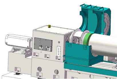
It is used to drive workpiece rotation and fixed at the left end of the machine bed. It has 3 manual speed gears with stepless speed regulation within each gear range. The motor drives spindle rotation through coupling and gearbox. A manual chuck is mounted at the front end of the headstock for workpiece clamping.
Gears are precision‑ground. Gear tooth surfaces are high‑frequency quenched to achieve high strength, high hardness, excellent wear resistance and high fatigue limit, so as to bear relatively large alternating load and impact load. Circulating lubrication with lubricating oil is adopted to extend service life of gears and bearings.
1.3.7 Drill Box Section
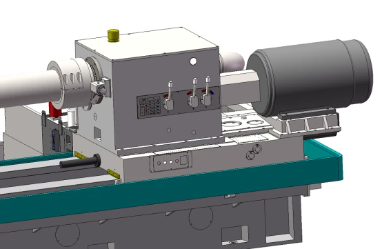
Mounted on the feed carriage, it is used to drive tool rotation. It is equipped with 12‑speed manual gear shifting. The motor drives the spindle to rotate via coupling and gearbox. A tool shank adapter is fitted at the front end of the spindle for clamping the tool bar.
The gears are precision‑ground. Gear tooth surfaces are high‑frequency quenched to achieve high strength, high hardness, excellent wear resistance and high fatigue limit, so as to withstand relatively large alternating loads and impact loads.
Circulating oil lubrication is adopted to extend the service life of gears and bearings.
The drill box is designed with two modes: rotating and fixed. The drill box can be locked when tool bar rotation is not required.
1.3.8 Closed‑type Center Rest
It is used for workpiece support. Adopting three‑point closed‑type center rest structure, it is equipped with two lower rollers and one upper roller, and the rollers are fitted with tapered roller bearings. The transverse position of the two lower rollers is adjusted by lead screws. The position of the center rest on the machine bed guideways is manually adjusted via gear‑rack mechanism. It mainly serves to support the workpiece.
As an auxiliary fixture for workpiece clamping, the closed‑type center rest can be applied for drilling of slender shafts, as well as for machining of long workpieces with large diameters.
1.3.9 Oil Feeder (Spindle‑type Structure)
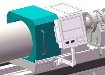
It functions for tool guiding, oil supply and supporting. Driven by servo motor for axial movement, it adapts to machining of workpieces with different lengths, and realizes pressing‑on and releasing of workpieces. Cooling and hydraulic pressure gauges of the machine are mounted on the front face of the oil feeder, enabling real‑time display during machining for operators to conveniently judge the machining status.
The oil feeder is driven by servo motor to press against or release the workpiece, featuring high precision and high rigidity. The oil feeder adopts an integral box‑type structure with high precision and high rigidity.
For convenient machine operation, the oil feeder is of unique design. Switching between drilling and boring can be realized merely by replacing corresponding tools and accessories. No backward displacement of the oil feeder will be caused by excessive oil pressure during drilling or boring process.
1.3.10 Feed System
Driven by servo motor, power is transmitted through reduction gearbox, then drives the carriage via gear‑rack mechanism to realize rapid traverse and working feed of the carriage. The feed is steplessly adjustable with feed rate ranging from 0.5 mm/min to 1000 mm/min.
1.3.11 Tool Bar Support
It supports the tool bar and controls the moving direction of the drill bar. It adopts high‑rigidity monolithic structure fitted with support sleeves, which can absorb shocks, vibrations and other loads generated during machining.
1.3.12 Cooling System
It mainly consists of cooling pump, chip collecting box, oil tank and other components, supplying sufficient cutting oil for deep‑hole machining.
It is an above‑ground oil tank fabricated by full welding of high‑quality steel plates.
Telescopic protective covers are installed between chip collecting boxes on the oil tank to fully cover the oil tank and prevent foreign debris from falling into it.
Numerical values of cutting oil pressure, liquid level, oil temperature and flow rate are digitally displayed on the operation station.
2. Main Machine Parameters
Technical Specifications
Machining range Drilling range: Φ30~Φ150 mm
Push‑boring range: Φ40~Φ500 mm
Trepaning range: Φ120~Φ400 mm
Maximum machining depth range: 0.5 m ~ 8 m
Workpiece length range: 0.5 m ~ 8 m
Machine performance
Z1‑axis (feed carriage)
Feed speed range: 0.5~1000 mm/min, stepless adjustment
Servo motor: 35 Nm / 5.5 kW, servo motor
Z2‑axis (oil feeder movement)
Rapid traverse speed: 1.5 m/min
Servo motor torque: 27 Nm / 4.3 kW, servo motor
Headstock
Spindle speed range: 4~440 r/min
Motor power: 45 kW, variable‑frequency motor
Spindle front taper bore: Metric 140
Chuck: Φ630 mm, manual three‑jaw type
Drill box
Speed range: 40~500 r/min
Motor power: 30 kW, standard motor
Cooling system
Maximum pressure: 2.5 MPa
Maximum flow rate: 800 L/min
Oil tank capacity: 6600 Liters
Cooling motor power: 7.5 kW for 3 sets; 15 kW for 1 set
Others
Height from spindle center to top surface of guideway: 625 mm
Maximum swing diameter over bed: Φ1250 mm
Clamping diameter range of center rest: Φ100~Φ750 mm
Total installed power of machine: 138 kW
Machine load‑bearing capacity: 15 tons
Machine floor space: 26 m × 3.8 m
Approximate machine weight: 35 tons
4.Contact Me:
Email:sale@dzgaunlu.com
Wahtsapp:+8613853423246
Hot Tags: tsk2150×8m cnc deep hole drilling & boring machine, China, suppliers, manufacturers, factory, customized, price, cheap, company, cost, for sale
You Might Also Like