Latest Products
Contact Us
Add: No.21, D Zone Jingjinluji Industry Park, Xingfu Road, Dezhou City, Shandong, China
Whatsapp/Wechat: +8615165964868
SKYPE: susanleeguobin
Email: dzguanlu@dzguanlu.com
Official webiste: www.dzgljc.com

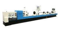
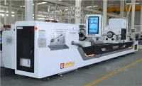
ZSK2106 CNC Deep Hole Drilling Machine
This machine is equipped with drilling function. Drilling: BTA drilling method. Cutting oil is fed to the tool through the gap between the oil feeder, the drill rod and the hole wall, and the cutting oil carries chips out through the inner bore of the drill rod. Machine operating mode: The workpiece rotates at low and constant speed for deviation correction. The tool rotates at high speed to meet the cutting speed requirement, and the tool speed is infinitely variable.
Description

1. Machine Overview
1.1 Machining Method
This machine is designed for drilling operations.
Drilling: BTA drilling process. Cutting oil is supplied to the cutting tool via the clearance between the oil feeder, drill rod and hole wall. The oil carries chips out through the inner bore of the drill rod.
Machine operation: The workpiece rotates at low constant speed for deviation correction. The cutting tool rotates at high speed to meet the required cutting speed, with infinitely variable speed regulation for the tool.

1.2 Machine Machining Range
Drilling range: φ20–φ60 mm
Maximum drilling depth: 3000 mm
Maximum workpiece length: 3000 mm
1.3 Main Machine Structure
1.3.1 Main Components
Bed, headstock, oil feeder, drill rod support, drill head box, cooling system, control system, electrical cabinet, workpiece rest, steady rest, etc.
1.3.2 Workpiece Clamping
One end of the workpiece is clamped by the manual three-jaw chuck on the headstock, and the other end of the workpiece is automatically pressed by the taper disc of the oil feeder.

1.3.3 Machine Control System
Control system: SIEMENS 808D Z-axis: Longitudinal feed movement of the drill head box, driven by a servo motor through a servo reducer to drive the ball screw. Main control functions: workpiece rotation, tool rotation, tool feed, cooling system, etc.
1.3.4
Basic parts such as boxes, bed and slide plate are precision cast from high-quality cast iron. After casting, they undergo two stress relief treatments to eliminate internal stress, stabilize structure and dimensions, and improve mechanical properties.
1.3.5 Machine Bed
The bed is resin sand cast and normalized after casting. The bed adopts a split structure, assembled with high-strength bolts and positioned by taper pins.
The tool bed is equipped with double rectangular slideways, precision ground with high hardness after surface quenching. A ball screw is fitted inside the tool bed for tool feed transmission. A rack is mounted on the side of the tool bed for manual adjustment of the drill rod support position.
Heavy-load ball linear guides are installed on the workpiece bed, together with a T-slot worktable. The headstock and steady rest can be moved manually along the linear guides for easy and quick adjustment.
V-shaped inclined ribs are arranged inside the bed to provide high supporting strength and resist deformation. The outer wall of the bed directly supports the guides, enabling the guides to withstand heavy cutting forces with high rigidity. This minimizes deformation and chatter during machining, helping improve machining quality and efficiency.
An oil return groove is cast around the bed, with oil shields installed on the groove. Cutting oil on the bed flows back to the cooling oil tank automatically.
1.3.6 Headstock
It is used to drive workpiece rotation and is mounted on the linear guides of the workpiece bed.
The main motor drives the spindle via belts and a gear reducer for fixed spindle speed. A manual three-jaw chuck is fitted at the front end of the headstock for workpiece clamping. A chip hopper is installed at the rear end of the headstock spindle for chip removal during boring.
The whole headstock can be moved manually axially along the linear guides of the workpiece bed and locked onto the worktable by locking blocks once positioned.
A button panel is mounted on the headstock housing, featuring spindle inching, spindle clamping, spindle unclamping and emergency stop functions.

1.3.7 Oil Feeder
It functions for tool guiding, cutting oil supply and drill rod support.
The oil feeder is installed in the middle of the bed. It moves axially under the control of the hydraulic system to clamp and release the workpiece.
A drill rod support sleeve is fitted on the right side of the oil feeder to support the drill rod.
A guide sleeve and taper disc are mounted on the left side of the oil feeder. The taper disc locates the workpiece, and the guide sleeve guides the cutting tool.
1.3.8 Drill Head Box
It drives the rotation of the cutting tool and is mounted on the feed slide plate.
A servo spindle motor drives the spindle rotation via belts and pulleys, with infinitely variable speed.
A shank adapter is assembled at the left end of the spindle for tool clamping.
The main motor adopts front-mounted drive for spindle rotation. The motor tail is kept away from the shank adapter, which helps prevent oil ingress into the motor, extend motor service life and facilitate tool change.
A button panel is installed on the housing, with functions of spindle inching, forward movement, backward movement and emergency stop.
1.3.9 Drill Rod Support
It is used to support the drill rod. It adopts a high-rigidity monolithic structure fitted with a support sleeve, which can absorb shocks, chatter and other vibrations generated during machining. An automatic pulling mechanism is equipped. When retracting the tool, the feed slide plate can pull the drill rod support back to its home position automatically. Meanwhile, a manual adjustment gear is mounted on the support, allowing manual adjustment of the drill rod support position on the bed.
1.3.10 Cooling System
It mainly consists of cooling pump, chip conveyor, oil chiller, filter unit and oil tank, supplying sufficient cutting oil for deep hole machining. The oil tank is floor-mounted and fully welded with high-quality steel plates. Chip conveyor: removes chips and realizes preliminary separation of oil and chips. Oil chiller: keeps oil temperature within a reasonable range. It starts automatically when oil temperature exceeds the upper set limit and stops automatically when oil temperature drops below the lower set limit. Filter unit: adopts paper band filtration with automatic paper feeding function to improve the cleanliness of cutting oil. The pressure, liquid level, temperature and flow rate of cutting oil are digitally displayed on the operator station.
1.3.11 Feed Slide Plate
It drives the axial movement of the cutting tool. An automatic lubrication station supplies timed and metered lubrication to the sliding guide surfaces and screw nuts. A button panel is fitted on the slide plate, with functions of drill head box spindle inching, feed forward, feed backward and emergency stop.
1.3.12 Lubrication System
The sliding guide surfaces and screw nuts of the feed slide plate are lubricated by an automatic lubrication station with timed and metered oil supply, equipped with low liquid level alarm. Bearings of the headstock are lubricated by an automatic lubrication station with timed and metered oil supply, equipped with low liquid level alarm. Bearings of the drill head box are lubricated by an automatic lubrication station with timed and metered oil supply, equipped with low liquid level alarm. The slide plate of the drill rod support is lubricated by a manual lubrication pump.
1.3.13 Workpiece Rest
It is used for pre-positioning of the workpiece. The operator places the workpiece on the workpiece rest first. After the workpiece is clamped and positioned, it leaves the rest.
2.Main Machine Parameters
Technical Specifications
Machining Range
Drilling range: Φ20~Φ60mm
Machining depth: 3000mm
Workpiece length range: 300–3000mm
Workpiece outer diameter range: Φ30~Φ150mm
Machine Performance
Z-axis (Drill head box feed)
Feed speed range: 5~1000mm/min
Rapid traverse speed: 4000mm/min
Servo motor torque / power: 22Nm / 3.5kW
Drill head box
Speed range: 200~2000r/min
Motor power: 22kW, servo spindle motor
Headstock
Rotating speed: 20r/min
Motor power: 3.7kW
Chuck outer diameter: Φ250mm, manual three-jaw chuck
Others
Total machine power: 50kW
Tool bed guideway width: 490mm
Workpiece bed guideway size: 45
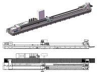
Machine footprint: 10m × 3.2m
Steady rest clamping range: Φ30~Φ150mm
Cooling System
Maximum pressure: 2.5MPa
Maximum flow rate: 200L/min
Pump unit: One set of 7.5kW variable frequency pump unit, one set of 7.5kW fixed displacement pump unit
Tank volume approx.: 2000L
4.Contact Me:
Email:sale@dzgaunlu.com
Whatsapp/Wechat:+8613853423246
Hot Tags: zsk2106 cnc deep hole drilling machine, China, suppliers, manufacturers, factory, customized, price, cheap, company, cost, for sale
You Might Also Like