Latest Products
Contact Us
Add: No.21, D Zone Jingjinluji Industry Park, Xingfu Road, Dezhou City, Shandong, China
Whatsapp/Wechat: +8615165964868
SKYPE: susanleeguobin
Email: dzguanlu@dzguanlu.com
Official webiste: www.dzgljc.com
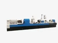
CNC Deep Hole Drilling And Boring Machine
CNC deep hole drilling and boring machine
Description
Deep hole drilling machine Introduction to machine tool performance:
Deep hole drilling machine Main functions of the machine tool:
This machine tool is a special machine tool for processing cylindrical deep hole parts, which is suitable for processing various hydraulic cylinders, spindle holes, cylinder holes, cooling holes, etc. The hole size accuracy of the machined workpiece can reach IT7 ~ IT10, and the surface roughness of the inner hole can reach Ra3.2 ~ 12.5 μm.
All the castings of this machine tool adopt the design concept of box structure, and the optimization design is carried out through finite element analysis, which makes it have the characteristics of reasonable quality, high rigidity and high precision.
All castings of the machine tool are made of high-strength cast iron and resin sand molding. After all castings are cast, they are normalized, and after roughing, they are normalized again. Eliminate the internal stress generated in the casting process and remove the machining stress generated in rough machining, so that it has good accuracy and stability.
Deep hole drilling machine Machine tool processing, clamping and chip removal methods:
2.1 Machine tool processing method:
Method 1: The workpiece and the tool rotate at the same time and the tool is fed.
Method 2: The processing method of workpiece rotation and tool feed.
2.2 Machine tool clamping method:
When machining holes below Φ500, the oil pressure head supplies oil, and the coolant is wrapped with iron filings to discharge the chips in the direction of the headstock. Workpiece clamping mode, the end of the bedside box is clamped by a chuck; The middle is supported by idler rollers or center frame; The feeder end is tightly tightened and sealed with a conical disc (or flat disc).
When machining Φ500 ~ Φ800 holes, open boring is adopted, oil is supplied through the tail end of boring bar, and the coolant wrapped with iron filings is supplied to the middle chip discharge bucket in the direction of bed head box and the end of oil feeder. Workpiece clamping mode, the end of the bedside box is clamped by a chuck; The middle and right side are supported by idler rollers or center frames; The right end of the workpiece is placed in the middle chip discharge bucket, and a suitable chip discharge space is left with the oil pressure head end.
2.3 Chip removal method of the machine tool during processing:
Drilling: During BTA drilling, oil is supplied to the cutter through the oil feeder, and chips are removed by the inner hole of the cutter bar.
Boring: When machining holes below Φ500, the oil is supplied through the oil pressure ,and the bottom hole of the workpiece is used to remove chips.
When machining Φ500 ~ Φ800 holes, oil is supplied through the inner hole of the tool bar, and the bottom hole of the workpiece is used to remove chips.
Trepanning: supply oil to the tool through the inner hole of the tool bar, and use the gap between the tool bar and the hole wall to remove chips.
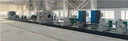
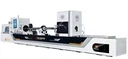
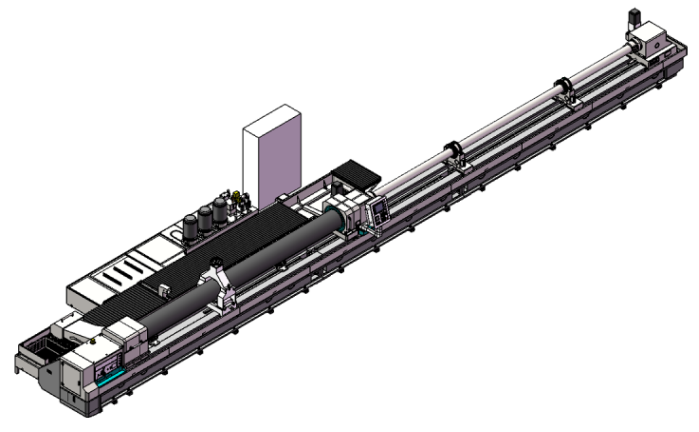
Overview of the overall layout of the machine tool and the structure of main components:

Note: The machine tool in the above picture is not the machine tool described in this scheme, but the overall layout is similar to the machine tool described in this scheme, for reference only!
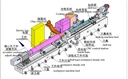
The overall layout of this machine tool: The machine tool consists of the main components such as bed body, bed head box, idler roller, center frame, oil feeder, boring bar bracket, drill pipe box, feed system, cooling system, CNC system, etc.
Bed:
The machine tool bed guide rail is a rectangular guide rail, which has high wear resistance after quenching; The bed adopts a split structure, which is assembled together by high-strength bolts and positioned by taper pins.
The total width of the bed is 1400mm, the total width of the two guide rails is 1250mm, the width of a single guide rail is 300mm, and the total height is 750mm. The machine tool bed is equipped with a high-precision rack, which is used for the movement of the drill pipe box feed carriage (Z1 axis), the servo jacking and rapid movement of the oil feeder (Z2 axis), and the manual movement of the center frame, boring bar bracket and other components.
Both sides of the bed adopt cast oil return groove structure, and install protection, which has excellent leakage-proof performance.

Bed end view
Headstock
The headstock is located at the far left end of the machine tool, and a chuck is installed at the front end of the spindle to grip the workpiece and drive the workpiece to rotate. The headstock of the machine tool is driven by the main motor through the gear set, which drives the spindle to rotate, realizes stepless speed regulation in the gear, and meets the machining requirements of each hole diameter.
The transmission gear of the headstock is made by precision grinding. The tooth surface of the gear has been quenched by high frequency, so that the gear has high hardness, high strength, high wear resistance and high fatigue limit, and can withstand relatively large alternating load and impact load.
The headstock adopts independent lubricating oil circulation lubrication, which is beneficial to improve the life of gears and bearings.

Headbox transmission system diagram
Support rollr and center frame:
The support roller of the machine tool is supported by rollers equipped with rolling bearings as working surfaces. Each set of rollers can be moved individually to be suitable for supporting workpieces with different outside diameters. The alignment and support range of the two rollers can be separately adjusted by the lead screw. After adjustment, the bracket body is locked by bolts. When working, the roller carriage plate is also locked on the bed by bolts to enhance the rigidity of the roller.
The center frame of the machine tool can be called an idler type center frame. Two supporting rollers in the lower part of the center frame are the same as the idler rollers. The supporting rollers in the upper part of the center frame and the supporting rollers in the lower part of the center frame are closed with three-point supporting center frame. All three rollers can be adjusted separately by adjusting the screw, and after adjustment, they are locked by bolts. When working, the center frame carrier is also locked on the bed by bolts to enhance the rigidity of the center frame.


Support roller center frame
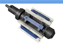
Oil pressure head:
Oil pressure head is the core component of deep hole machine tools, which is often used for tool guidance, cutting oil supply, supporting drill pipe, workpiece positioning, etc. At the head of the oil pressure, there is a tapered disc, which is used to position and tighten the workpiece. It is combined with the workpiece at a 60 ° taper angle, and the taper is customized according to the needs of the workpiece. The oil pressure head is movable to adapt to the machining of different length parts.
The oil pressure head of this machine tool is equipped with a set of oil pressure head spindle assembly for machining small holes. This oil feeder spindle assembly is used for drilling holes, and boring holes with bore diameters ≤ Φ500. The maximum outer diameter of the spindle assembly of the oil pressure head through the boring bar is Φ220mm; During drilling, the sealing method of the oil pressure head end can be selected according to the specific workpiece conditions. End face seal or conical disc seal can be selected.
The movement of the oil pressure head is by using a servo motor to drive the gear shaft to rotate through worm gears, gear components, etc., so that it moves linearly along the rack, thereby realizing the rapid movement of the oil pressure head and servo tightening (Z2 axis). The tightening force of the workpiece can be adjusted by controlling the torque of the servo motor.
Drill pipe box:
The drill pipe box is fixed on the feed carriage and is used to drive the cutter to rotate and feed. The drill pipe box of this machine tool uses a motor to drive the spindle to rotate through a gear set. The front end of the spindle is equipped with a drill pipe clamping sleeve for clamping the drill pipe.
The transmission gear of the drill pipe box is made by precision grinding. The tooth surface of the gear has been quenched by high frequency, so that the gear has high hardness, high strength, high wear resistance and high fatigue limit, and can withstand relatively large alternating load and impact load.
The drill pipe box is lubricated by independent lubricating oil circulation, which is beneficial to improve the life of gears and bearings.
Feed tray:
The drill pipe box is fixed on the carriage of the feed system. The feed system is composed of servo motor, precision planetary reducer, gear, gear shaft, etc. The motor is driven by the reducer, gear, etc. to drive the gear shaft to rotate, so that the carriage plate moves linearly along the rack, thereby realizing the carriage plate of the feed system. Rapid movement and feed movement. The feed system adopts the anti-backlash structure design of double gear shaft, which is beneficial to improve the motion accuracy and stability of the feed system.
Boring bar bracket:
The boring bar bracket is used as an auxiliary support for the boring bar. It is used to support the boring bar. A support sleeve is installed on it, which can absorb the impact and vibration generated during the processing.
The movement of the boring bar bracket along the bed guide rail is pushed by the carriage plate, or it can be moved by manual device. When replacing the boring bar, the corresponding support sleeve must be replaced. The number of boring bar brackets equipped with this machine tool is set according to the machine tool specifications to meet the requirements of different workpieces. Brackets are evenly distributed when in use.
Cooling System:
The main function of the cooling system is to use circulating liquid medium to lubricate and cool the cutting area, and remove chips at the same time. The cooling system adopts an above-ground fuel tank structure.
The cooling system mainly consists of fuel tank, pumping station, oil pipeline, chip storage truck and oil return tank. The function of cooling oil is to cool and remove chips. The cooling system is an oil supply system composed of a pump and a motor. By adjusting the start-stop combination of the motor, different flows can be obtained, which is generally enough to meet the processing requirements.
The valve group of the cooling system divides the cooling oil into two ways, one way supplies oil to the oil feeder and the other way supplies oil to the tail end of the drill pipe box, which can be selected and used according to the usage situation.
Control System:
The independent electrical cabinet has good dustproof effect. The cabinet is equipped with an air-conditioning cooling system, which makes the electrical components work in a suitable temperature environment, thus prolonging the service life of the components and ensuring the stability and reliability of the control system. The CNC system is Siemens 828D CNC system.
The safety function in the machine tool control system, when some failures occur during machine tool processing, can be reacted by the torque limiting unit and stop running in time to protect the safety of machine tools, tools and workpieces within a certain range.
Technical data:
Foundation and installation plan, general machine tool drawing, operation instructions, numerical control and program instructions, electrical instructions.
Uncovered matters shall be negotiated by both parties.
Table 1:Deep hole drilling machine Main technical parameters of machine tool
|
Items |
Primary parameters |
remark |
||
|
Processing range |
Range of drilling diameter |
Φ60 ~ Φ200mm |
||
|
Boring diameter range |
Φ100 ~ Φ800mm |
|||
|
Trepanning Diameter Range |
Φ150 ~ Φ800mm |
|||
|
Workpiece outer diameter range |
Φ200 ~ Φ1250mm |
|||
|
Workpiece length range |
1000 ~ 8000mm |
|||
|
Maximum depth of machining |
8000mm |
|||
|
Machine tool performance |
Z1 axis (Drill Pipe Box Feed) |
Feed speed range |
0.5 ~ 3000mm/min |
|
|
Maximum fast moving speed |
4000mm/min |
|||
|
Servomotor torque |
7.7 kW/48Nm |
Siemens |
||
|
Z2 axis (Oil pressure head Movement) |
Maximum fast moving speed |
2000mm/min |
||
|
Servomotor torque |
7.7 kW/48Nm |
Siemens |
||
|
Headstock |
Speed range |
1 ~ 200r/min |
Manual four-speed regulation |
|
|
Motor power |
75kW |
Servo spindle motor |
||
|
Drill pipe box |
Speed range |
30 ~ 400r/min |
Manual three-speed adjustment |
|
|
Motor power |
75kW |
Servo spindle motor |
||
|
Support roller |
Support Range |
Φ600 ~ Φ1250mm |
||
|
Maximum load-bearing |
15 tons |
|||
|
Center frame |
Clamping range |
Φ200 ~ Φ800mm |
||
|
Maximum load-bearing |
15 tons |
|||
|
other |
Machine tool center height dimension |
900mm |
||
|
Total power of machine tool |
About 225kW |
|||
|
Maximum load bearing of machine tool |
20 tons |
|||
|
Cooling system |
Flow Range |
300, 600, 900L/min |
Constant flow adjustment |
|
|
Maximum pressure |
25bar |
|||
|
Cooling pump motor |
18.5 kW (three groups) |
|||
Contact :
Lean Lee
Mob : 008615153489973
Email : export@dzguanlu.com
Hot Tags: cnc deep hole drilling and boring machine, China, suppliers, manufacturers, factory, customized, price, cheap, company, cost, for sale
You Might Also Like