Latest Products





Contact Us
Add: No.21, D Zone Jingjinluji Industry Park, Xingfu Road, Dezhou City, Shandong, China
Whatsapp/Wechat: +8615165964868
SKYPE: susanleeguobin
Email: dzguanlu@dzguanlu.com
Official webiste: www.dzgljc.com

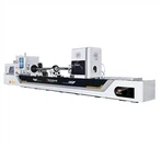
ZSK2312F Compound CNC Deep Hole Drilling Machine
1. Machine Overview 1.1 Processing Modes The machine is equipped with two processing modes: gun drilling and BTA drilling. BTA Drilling: Cutting oil is supplied to the tool through the gaps between the oil feeder, the tool rod and the hole wall, and discharges chips through the inner hole of the tool rod. Gun Drilling (External Chip Removal): Cutting oil is fed through the rotary joint at the tail end of the spindle of the drill rod box, passes through the inner hole of the tool rod to the cutting position, and carries chips out through the gap between the V-shaped groove of the tool rod and the hole wall. Gun drilling and BTA drilling share one set of spindle. Switching between the two processing modes can be realized by manually replacing tools and accessories and switching the oil circuit.
Description
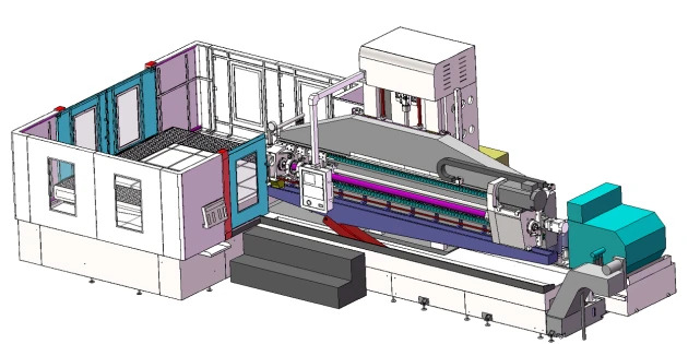
1. Machine Overview
1.1 Processing Modes
The machine is equipped with two processing modes: gun drilling and BTA drilling.
BTA Drilling: Cutting oil is supplied to the tool through the gaps between the oil feeder, the tool rod and the hole wall, and discharges chips through the inner hole of the tool rod.
Gun Drilling (External Chip Removal): Cutting oil is fed through the rotary joint at the tail end of the spindle of the drill rod box, passes through the inner hole of the tool rod to the cutting position, and carries chips out through the gap between the V-shaped groove of the tool rod and the hole wall.
Gun drilling and BTA drilling share one set of spindle. Switching between the two processing modes can be realized by manually replacing tools and accessories and switching the oil circuit.
1.2 Machine Processing Range
Gun drilling range: φ10-φ25mm
BTA drilling range: φ25-φ120mm
Maximum processing depth: 2800mm
1.3 Main Machine Structure
1.3.1 Conversion between Gun Drilling and BTA Drilling
1.3.1.1 Oil Circuit Conversion
The cooling system is equipped with two sets of pumps, one for gun drilling oil supply and the other for BTA drilling oil supply. Each pump set corresponds to an independent control code, and the matching code shall be selected during programming.
1.3.1.2 Drill Rod Box Conversion
In BTA drilling mode, the spindle of the drill rod box serves as the chip removal channel. A chip discharge hopper is mounted at the spindle tail end, and a chuck for tool rod connection is installed at the spindle front end. In gun drilling mode, the drill rod box spindle serves as the oil supply channel. A rotary joint is installed at the spindle tail end, and a chuck for tool rod connection is equipped at the spindle front end.
1.3.1.3 Guide Frame Conversion
In BTA drilling mode, the guide frame acts as the oil supply channel. A guide sleeve is fitted on the left end and a support sleeve on the right end of the guide frame, through which cutting oil is delivered to the tool. In gun drilling mode, the guide frame acts as the chip removal channel. With a guide sleeve on the left end and a support sleeve on the right end, chips are discharged through the hollow cavity in the middle of the guide frame.
1.3.2 Machine Control System
Control System: KND
X-axis: Realizes transverse movement of the worktable. Adopts heavy-duty roller linear guides. The ball screw is driven by a servo motor via a servo reducer under CNC control.
Y-axis: Realizes tool lifting movement. Adopts heavy-duty roller linear guides. The ball screw is driven by a servo motor via a servo reducer. It is equipped with a counterweight device and a brake-equipped servo motor, with CNC control.
Z-axis: Realizes tool feed movement. Adopts heavy-duty roller linear guides. The ball screw is driven by a servo motor through a reduction mechanism under CNC control.
Main control functions: X-axis, Y-axis and Z-axis movements, tool rotation, cooling system and other functional modules.
1.3.3
The base components including cabinet, machine bed, support plate, column and worktable are precision-cast from high-quality HT300 cast iron. All castings are subjected to two aging treatments after casting to eliminate internal stress, stabilize structural structure and dimensional accuracy, and optimize mechanical properties.
1.3.4 X-axis
The CNC system controls the transverse movement of workpieces with a travel of 2500mm.
Equipped with heavy-duty roller linear guides, featuring large load capacity and low running resistance.
The ball screw is driven by a servo motor through a servo reducer, ensuring long service life and high positioning accuracy.
The ball screw adopts a double-nut structure, which is lubricated at fixed time and quantity by an automatic lubrication station. Special screw bearings are installed at both ends of the screw, adopting a fixed-free extended bearing mounting structure.
Telescopic stainless steel guards and foot pedals are installed on the guide rails to facilitate operation and protect the guide rails and ball screws.
During drilling, the worktable is automatically locked on the X-axis machine bed by the hydraulic system.

1.3.5 Y-axis
It controls the vertical lifting movement of the cutting tool with a travel of 1600 mm. It mainly consists of lifting slide carriage and column.
Double rectangular sliding guides are adopted. The guide surfaces are quenched and precision ground with hardness of HRC48–52, featuring heavy load capacity and low wear rate.
The ball screw is driven by a servo motor via a servo reducer, delivering long service life and high positioning accuracy.
The ball screw adopts a double-nut structure, lubricated at fixed time and fixed quantity by an automatic lubrication station. Special ball screw bearings are installed at both ends of the screw, adopting a fixed-tension bearing arrangement (one end fixed, the other free to extend).
During drilling operations, the lifting slide carriage is automatically locked onto the Y-axis column by the hydraulic system, and counterweight blocks are equipped for weight balancing.
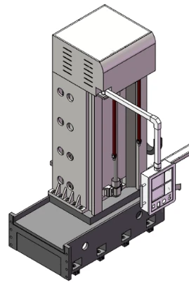
1.3.6 Z-axis
It controls the feeding motion of the cutting tool to meet the deep drilling depth requirement of the machine.
Heavy-duty roller linear guides are adopted, which feature large load capacity and low running resistance.
The ball screw is driven by a servo motor through a servo reducer, offering long service life and precise positioning.
The ball screw is of double-nut structure, lubricated regularly and quantitatively by an automatic lubrication station. Special bearings for ball screws are mounted at both ends, adopting a bearing configuration with one end fixed and the other tensioned.
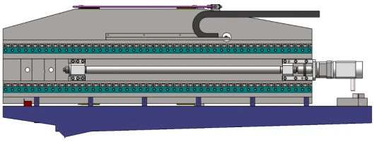
1.3.7 T-slot Worktable
Dimensions: X-axis × Z-axis = 2800mm × 2200mm; T-slot width: 28mm Foot pedals are fitted on the worktable for convenient machine operation.
1.3.8 Drill Rod Box
It controls the rotation of cutting tools. The servo main motor drives the spindle from the front after speed reduction, which facilitates tool replacement and protects the main motor. The spindle output speed is steplessly adjustable. Sets of high-speed angular contact ball bearings are mounted on the spindle, lubricated at fixed time and quantity by an automatic lubrication station. One set of spindle is shared for both gun drilling and BTA drilling modes.
1.3.9 Drill Rod Support
The support sleeves mounted on the drill rod support and the support sleeve fitted at the right end of the guide frame jointly support the tool rod to improve its rigidity. The drill rod support is mounted on two linear guide sliders and pulled back by the drill rod box via a chain.
1.3.10 Guide Frame
It is shared by both gun drilling and BTA drilling processes. It performs chip removal during gun drilling. It supplies cutting oil to the tool during BTA drilling. Controlled by the hydraulic system, the guide frame automatically clamps and releases workpieces.
1.3.11 Cooling System
Components: chain plate chip conveyor, circulating pump, drum-type paper tape filter, oil chiller, pump unit, liquid level sensor, flow sensor, pressure sensor, temperature sensor and oil tank.
Gun drilling pump unit: 1 set of gear pump with variable-frequency motor (variable-frequency pump), maximum flow rate of 100L/min. BTA pump unit: 2 sets of vane pumps with standard motors (fixed-displacement pumps), maximum flow rate of 300L/min.
The cooling system is equipped with multiple sensors. The liquid level, oil temperature, flow rate and pressure values are displayed on the instrument panel. The ground-mounted oil tank is fully welded with high-quality steel plates.
Chip conveyor: removes cutting chips and realizes preliminary separation of oil and chips. Oil chiller: keeps the oil temperature within a reasonable range. It starts automatically when the oil temperature exceeds the preset upper limit and stops automatically when the temperature drops below the preset lower limit. Filter: adopts paper tape filtration with automatic paper feeding function to improve the cleanliness of cutting oil.
1.3.12 Hydraulic System
It controls the axial movement of the guide frame to clamp or release workpieces. It controls the hydraulic clamping plates of the worktable and lifting slide to lock the worktable and lifting slide.
1.3.13 Lubrication System
The sliding guide surfaces of the lifting slide, the linear guide sliders of the worktable and drill rod box, and the spindle bearings of the drill rod box are lubricated at fixed time and quantity by an automatic lubrication station, which is provided with a low liquid level alarm function.
The guide sliders of the tool rod support and guide frame are lubricated by a manual lubrication pump.
2. Main Machine Parameters
Technical Specifications and Parameters (Remarks Attached)
Machining Range
Drilling diameter range for gun drilling: Φ10~Φ25mm
Drilling diameter range for BTA deep hole drilling: Φ25~Φ120mm
Maximum machining depth for gun drilling: 2800mm
Maximum machining depth for BTA deep hole drilling: 2800mm
Machine Performance
X Axis
Rapid traverse speed: 3000mm per minute
Servo motor specification: 48Nm / 7.5KW
Travel stroke: 2500mm
Guide rail type: heavy load roller linear guide rail
Guide rail model size: 55
Ball screw diameter specification: φ80
Y Axis
Rapid traverse speed: 3000mm per minute
Servo motor specification: 35Nm / 5.5KW
Travel stroke: 1600mm
Ball screw diameter specification: φ63
Guide rail effective width: 1500mm
Z Axis
Feed speed adjustable range: 5~1000mm per minute
Rapid traverse speed: 4000mm per minute
Servo motor specification: 23Nm / 3.6KW
Guide rail type: heavy load roller linear guide rail
Guide rail model size: 55
Ball screw diameter specification: φ80
Drill Headstock
Spindle rotation speed range: 200~2000 revolutions per minute
Spindle motor power: 55KW, servo spindle motor
Worktable
Worktable overall dimension in X and Z directions: 2800mm × 2200mm
T-slot width: 28mm
Maximum bearing load capacity: 36 tons
General Machine Data
Total installed power of the whole machine: 115KW
Total machine weight: 55 tons
Machine floor space dimension: 10.5m × 6.2m
Maximum length-to-diameter ratio for deep hole drilling: 150:1
Cooling System
Gun Drilling Cooling Circuit
Maximum hydraulic working pressure: 8MPa
Maximum coolant flow rate: 100 liters per minute
Coolant pump assembly: one set of gear pump matched with 7.5KW variable frequency motor
BTA Deep Hole Drilling Cooling Circuit
Maximum hydraulic working pressure: 4MPa
Maximum coolant flow rate: 300 liters per minute
Coolant pump assembly: two sets of vane pumps matched with 11KW motors
Oil chiller cooling capacity: 12KW
Chip conveyor effective width: 500mm
Coolant filtration precision: 40μm
Total volume of coolant tank: 2500 liters
Contract Me:
Email:sale@dzguanlu.com
Whatsapp:+8613853423246
Hot Tags: zsk2312f compound cnc deep hole drilling machine, China, suppliers, manufacturers, factory, customized, price, cheap, company, cost, for sale
You Might Also Like