
Latest Products

Contact Us
Add: No.21, D Zone Jingjinluji Industry Park, Xingfu Road, Dezhou City, Shandong, China
Whatsapp/Wechat: +8615165964868
SKYPE: susanleeguobin
Email: dzguanlu@dzguanlu.com
Official webiste: www.dzgljc.com
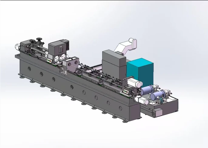
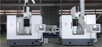
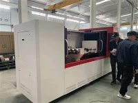
ZLK2102 × 2 CNC Deep Hole Drilling Reaming And Broaching Machine
**2. Machine Overview** **2.1 Machine Purpose** The ZLK2102 × 2 CNC deep hole drilling reaming and broaching machine is designed for coaxial hole machining of cylindrical workpieces. The ZLK2102 × 2 CNC deep hole drilling reaming and broaching machine features a dual-spindle...
Description
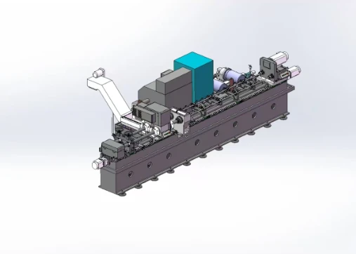
The ZLK2102 × 2 CNC deep hole drilling reaming and broaching machine is designed for coaxial hole machining of cylindrical workpieces. The ZLK2102 × 2 CNC deep hole drilling reaming and broaching machine features a dual-spindle structure, enabling simultaneous machining of two workpieces. The drill rod box controls tool rotation; the Z-axis controls tool feed; the X-axis controls headstock movement and incorporates a servo clamping function. The ZLK2102 × 2 CNC deep hole drilling reaming and broaching machine adopts a through-type headstock with chucks mounted at both ends. A steady rest combined with the headstock chuck is used for workpiece clamping. The headstock of the ZLK2102 × 2 CNC deep hole drilling reaming and broaching machine is equipped with a C-axis function, which, through two-axis interpolation with the Z-axis, enables helical groove machining.
The ZLK2102 × 2 CNC deep hole drilling reaming and broaching machine provides drilling, reaming, and broaching capabilities.
Drilling: Gun drilling is employed, with internal oil supply and external chip evacuation. Cutting oil enters the cutting edge through the internal bore of the tool shank and carries chips out through the clearance between the V-shaped groove of the tool shank and the hole wall.
Reaming: A deep-hole reamer is used to ream the internal bore. Cutting oil enters the cutting edge through the internal bore of the tool shank and carries chips out through the pre-drilled hole.
Broaching: A formed punch is used to broach the internal bore to the required profile. During broaching, workpiece rotation and tool travel are interpolated as two axes.
Machining sequence: drilling → external turning with the internal bore as reference → reaming → wire drawing.
Machine Parameters:
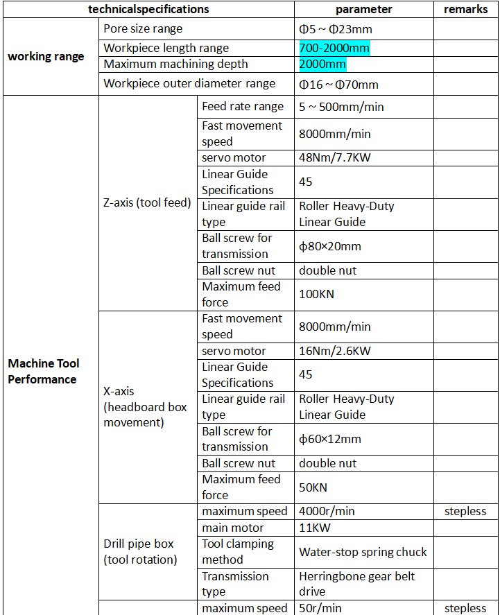
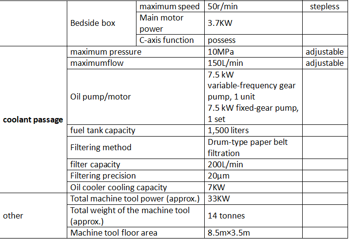
4. Description of the Machine Tool Structure
4.1 Installation of Tool-Related Components
4.1.1 Installation of the tool holder
The drill pipe box main shaft serves as an oil supply passage; a rotary joint is installed at the rear end of the main shaft, while a chuck for connecting the tool rod is installed at the front end of the main shaft.
4.1. Installation of tool-related components on the guide frame
The guide frame serves as a chip discharge channel. A conical disc and a guide sleeve are installed at the left end of the guide frame, while a support sleeve is installed at the right end; chips are discharged through the central cavity of the guide frame.
4.2 Mounting of the workpiece
The workpiece passes through the inner bore of the headstock spindle → the operator pushes the workpiece against the conical plate of the guide carriage, aligning the right ends of the two workpieces → the chuck at each end of the headstock spindle clamps the workpieces → the CNC system controls axial movement of the headstock, pushing the workpiece against the conical plate at the right end of the guide carriage → the center stand manually clamps the left end of the workpiece.
4.3 Rotation of the Tool
The tool is driven to rotate by the drill pipe box, with continuously variable speed control.
The servo motor drives the spindle rotation via a V-belt and pulley; the pulley is mounted at the front end of the spindle and provides the drive. This arrangement positions the rear end of the main motor toward the rear end of the spindle, thereby protecting the main motor and facilitating tool replacement.
A set of high-speed angular contact ball bearings is installed on the spindle; the bearings are automatically lubricated with timed and metered lubrication.
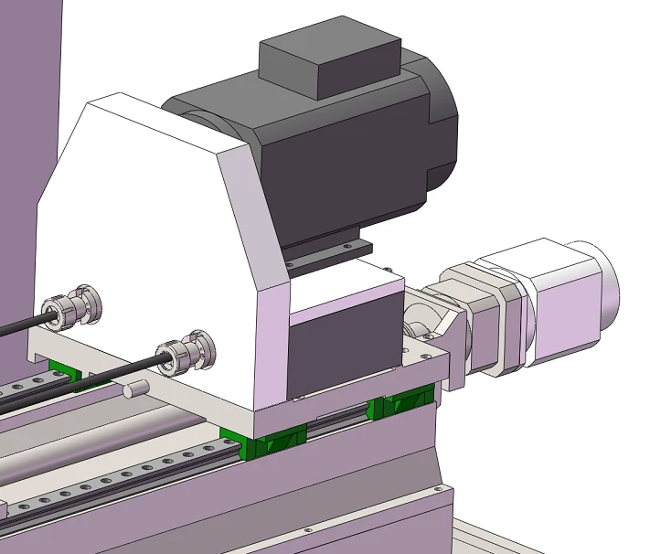
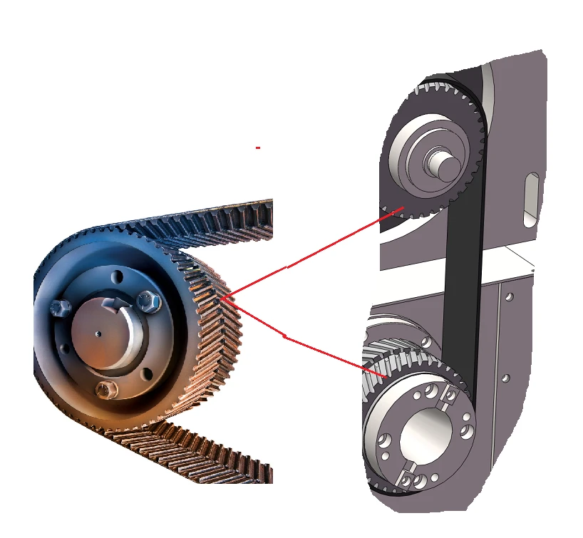
Schematic diagram of the drill pipe box drive (subject to the actual product)
4.4 Tool Feed System
The servo motor drives the ball screw via a servo reducer, thereby enabling the feed motion of the tool.
The nut on the ball screw features a double-nut configuration and utilizes automatic lubrication for timed, metered lubrication.
Specialized ball screw bearings are installed at both ends of the ball screw, employing a bearing configuration in which one end is fixed and the other end is tensioned.
4.5 Support for the tool post
The knife shank is supported by the support sleeve installed on the knife shank bracket and the support sleeve installed at the right end of the guide frame, thereby enhancing the rigidity of the knife shank.
The drill rod bracket is mounted on two linear guide sliders and can automatically adjust its spacing as the drill pipe box moves.
Exterior view of the blade holder bracket
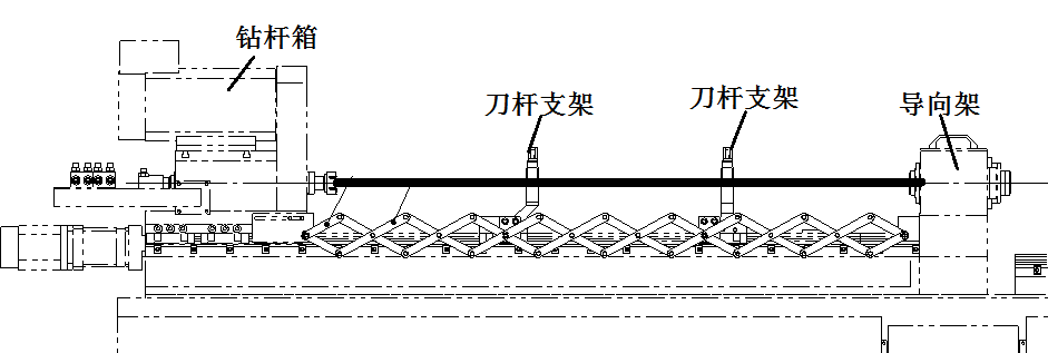
Schematic diagram of the blade shaft guide follower
4.6 Rotation of the workpiece
The workpiece is rotated by a bed-mounted drive box, and its rotational speed is continuously adjustable.
The servo spindle motor drives the spindle rotation via a synchronous belt and pulley, providing C-axis functionality.
The entire bedside box can move axially under the control of the CNC system, enabling adjustment of the axial position or clamping of workpieces for positioning; when clamping a workpiece, the moving guide rail is a ball linear guide in the servo motor's worktable torque mode.
A through-type headstock box allows the workpiece to pass through the spindle bore, with the workpiece clamped by the chuck at both ends.
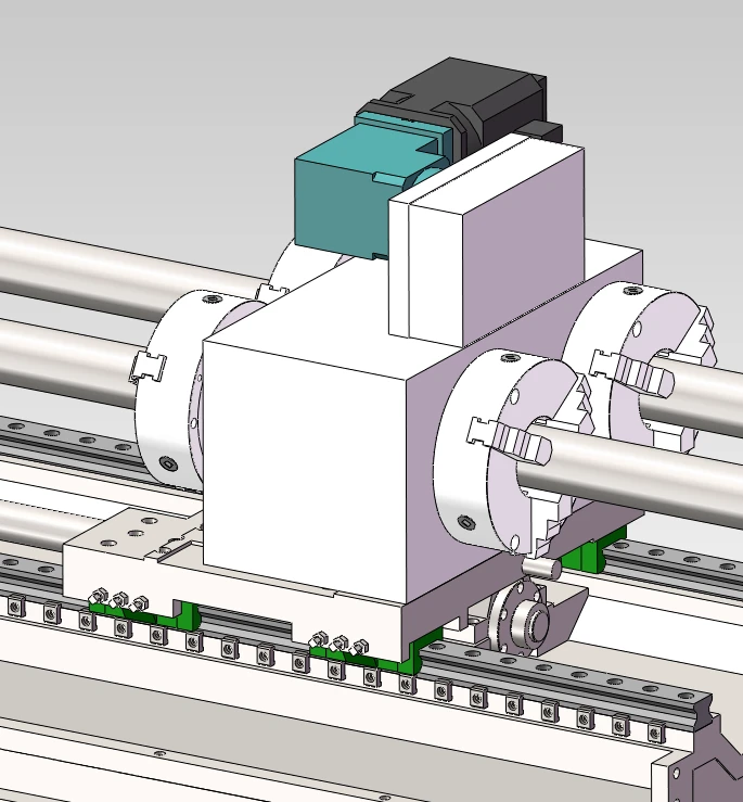
Schematic view of the bedside storage box
4.7 Cooling System
Components: chain plate chip remover, circulation pump, drum-type paper tape filter, oil cooler, pump assembly, liquid level sensor, flow rate sensor, pressure sensor, temperature sensor, and oil tank.
The pump unit is driven by a variable-frequency motor; the pump's output flow is adjusted by varying the motor speed, while a manual relief valve installed at the pump's oil outlet is used to regulate the pump's output pressure.
Various sensors are installed in the cooling system; liquid level, oil temperature, flow rate, and pressure are displayed on the instruments.
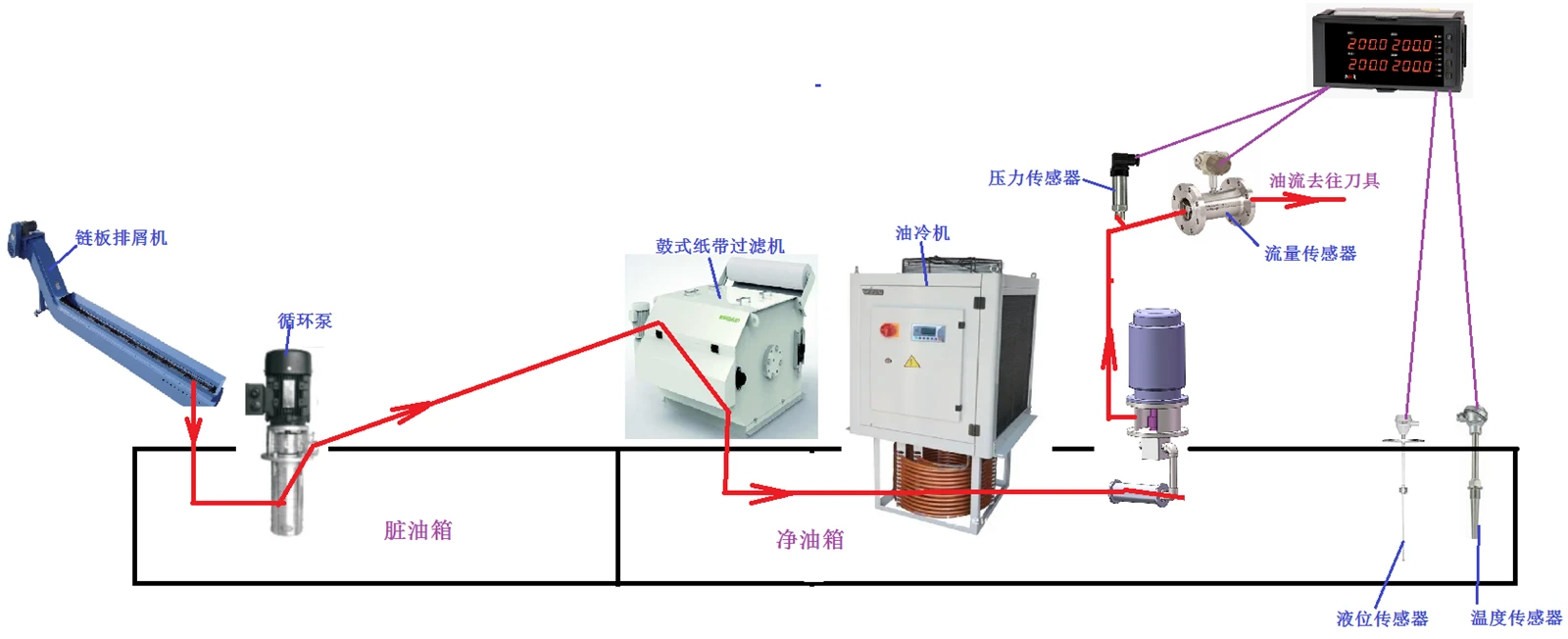
Cooling System Schematic
4.8 Control System
numerical control system:GSK
Primarily used for controlling: tool rotation, tool feed, workpiece rotation, the cooling system, the lubrication system, workpiece clamping and positioning, the center stand, and the coordinated motion of the C-axis and Z-axis, among other functions.
The operator simply needs to press the start button, and the machine tool will automatically complete the machining process according to the program.
4.9 Lubrication System
The linear guide sliders used for the movement of the drill pipe box and the lead screw nuts are supplied with automatic lubrication stations that provide timed and metered lubrication; the linear guide sliders used for the movement of the head box are likewise supplied with automatic lubrication stations.
Bonnie Lau Whatsapp/Wechat :+8615153489983
Email : info@dzguanlu.com
Hot Tags: zlk2102 × 2 cnc deep hole drilling reaming and broaching machine, China, suppliers, manufacturers, factory, customized, price, cheap, company, cost, for sale
You Might Also Like


