Latest Products


Contact Us
Add: No.21, D Zone Jingjinluji Industry Park, Xingfu Road, Dezhou City, Shandong, China
Whatsapp/Wechat: +8615165964868
SKYPE: susanleeguobin
Email: dzguanlu@dzguanlu.com
Official webiste: www.dzgljc.com

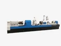
Bta Deep Drilling
Machine Appearance : Machine brief : 2.1 Machine processing capacity : Drilling diameter range : Φ25~Φ100mm Boring diameter range: Φ30~Φ100mm Workpiece OD range : Φ60~Φ400mm 2.2 Machine functions : Machine working mode : Workpiece rotate, cutting tool fix ; Workpiece...
Description
Machine Appearance:


Machine brief :
2.1 Machine processing capacity :
Drilling diameter range : Φ25~Φ100mm
Boring diameter range: Φ30~Φ100mm
Workpiece OD range : Φ60~Φ400mm
2.2 Machine functions :
Machine working mode : Workpiece rotate, cutting tool fix ; Workpiece rotate,cutting tool rotate in opposite direction and feed .
Drilling hole : BTA drilling method,cutting oil is supplied to the tool through the oil pressure head and gap between the drill bar and hole wall, and discharged through the inner hole of the drill bar with cutting chips.
Push boring hole : The cutting oil is supplied to the tool through the oil pressure head and gap between the drill bar and hole wall, and discharged through the basic hole of workpiece . During processing,the cutting tool move to the direction close to the headstock .
2.3 Machine main structure:
2.3.1 Main parts of machine
Machine bed, headstock , oil pressure head, drill bar support rest , drill box , sliding guide rail , Rack and pinion, coolant system , control system , electric cabinet, workpiece carrier etc. .
2.3.2 Workpiece clamping
The manual three-jaw chuck on the headstock clamps one end of the workpiece, and the cone disc on oil pressure head automatically tightens the other end of the workpiece. .

Workpiece clamping sketch
2.3.3 Machine control system
CNC system : DELTA PLC
Z axis:The longitudinal feed movement of the drill box, the servo motor drives the rack and pinion mechanism through the reducing mechanism.
X axis: Oil pressure head servo tighten the workpiece , the servo motor drives the rack and pinion mechanism through the reducing mechanism.
2.3.4 The machine bed , box body, carriage etc. basic parts are precisely cast by super casting iron, processed by twice aging treatment after casting ,to eliminate stress , stable the structure and size , improve the mechanical properties ,etc. .
2.3.5 Machine bed :
The machine bed is made of resin sand and normalised after casting. The bed adopts split structure, assembled with high strength bolts and positioned by cone pin.
Adopt double rectangular sliding guide rail, precision grinding, the guide rail surface is with high quenching hardness .
The helical rack which is treated by precision processing and quenching is mounted inside of machine bed ,used for cutting tool feeding transmission . The machine has large bearing capacity, good rigidity and stable transmission.
The V-shaped slant reinforced ribs are distributed inside of the machine bed , supporting strength is high, and it is not easy to deform; The outer wall of machine bed support the guide rail directly, so the guide rail could bear large cutting force, with good rigidity, not easy to deform and vibrate during machining, it is good for improving the processing quality and working efficiency of machine .
The oil returning slot mounted with oil shield is cast around the machine bed , so that the cutting oil on machine bed will return the coolant tank automatically .
2.3.6 Headstock :
Used to drive the workpiece to rotate, fixed on the left end of machine bed .
The spindle speed is stepless ,the servo spindle motor drives the spindle to rotate through belt and gear box , the manual three-jaw chuck is installed in front of headstock for clamping the workpiece .
The gears are machined by precision grinding , gear surface is quenched by high frequency quenching, so that the gears can obtain high strength, high hardness, high wear resistance and high fatigue limit, and can withstand relatively large alternating load and shock load.
The external lubrication oil tank is used for circulating lubrication of gears and bearings, and a low liquid level alarm device is installed inside the oil tank.
Install a button board on the headstock box, which has functions such as spindle jog, feed forward, feed backward, and emergency stop.

Headstock Appearance
2.3.7 Oil pressure head
Used for guiding the cutting tool, supplying cutting oil and supporting the drill bar .
Servo motor drives its axial movement to adapt the workpiece with different length, and to tighten and loosen the workpiece .The servo motor can work under torque mode or position mode .
The rotary bearings of oil pressure head are installed inside of the oil pressure head box, with good rigidity and high rotation accuracy .
The rotary seal is installed on the outside of the right end of the oil pressure head body for easy maintenance.
The drill bar support sleeve in installed on the right end of oil pressure head for supporting the drill bar .
The guide sleeve ,cone disc and oil shield are installed on left end of oil pressure head , cone disc is used for positioning the workpiece, and guide sleeve is for guiding the direction of cutting tool .
The oil shield is push-pull structure,the oil retention is mounted under the oil shield ,so that the cutting oil can return the oil tank .

2.3.8 Drill box
Used to drive the cutting tool to rotate, installed on the feeding carriage .
The speed of spindle is stepless, the servo spindle motor drives the spindle to rotate through belt,belt pulley and gear box .
The tool shank connection sleeve at left end of spindle for clamping the cutting tool.
The chips removal bucket is installed at the right end of spindle for discharging the cutting chips .
The gears are machined by precision grinding , gear surface is quenched by high frequency quenching, so that the gears can obtain high strength, high hardness, high wear resistance and high fatigue limit, and can withstand relatively large alternating load and shock load.
The external lubrication oil tank is used for circulating lubrication of gears and bearings, and a low liquid level alarm device is installed inside the oil tank.

Drill box appearance sketch
2.3.9 Drill bar support rest
Used to support the drill bar ;
Adopt a integrate structure with high rigidity , the support sleeve is mounted on it , which can absorb the impact, vibration, etc. generated during the processing.
Install an automatic hanging mechanism. When returning the tool, the feeding carriage can automatically pull the drill bar support rest back to its initial position.
Drill bar support rest appearance sketch
2.3.10 Coolant system :
Mainly composed of Cooling pump,chips box,oil tank etc. ,to supply enough cutting oil for deep hole processing .
Oil tank : Install on floor, doesn't need to dig a pit , and the oil tank is fully welded with the super steel sheet .
Install a retractable protective cover between the chips boxes on the oil tank to prevent debris from falling into the tank.
The pressure, liquid level, oil temperature, and flow rate of cutting oil can be displayed
digitally on the control station .

Coolant system sketch
2.3.11 Feeding carriage
Used for driving the cutting tool to move axially .
Lubricate the sliding guide surface timely and quantitatively with an auto lubrication station .
The button board is mounted on the carriage ,which has functions of drill box spindle jog,
feeding forward, feeding backward, emergency stop.
2.3.12 Lubrication system
The sliding guide rail surface of the feeding carriage adopts automatic lubrication station for timed and quantitative lubrication, with a low liquid level alarm function .
The bearings and gears of the headstock are circulating lubricated by an independent external oil tank, and have a low liquid level alarm function.
The bearings and gears of the drill box are circulating lubricated by an independent external oil tank, and have a low liquid level alarm function.
The oil pressure head carriage, drill bar support rest carriage are lubricated by manual
lubricating pump .
2.3.13 Workpiece carrier
Used for workpiece pre-positioning .
The operator places the workpiece on the workpiece carrier first, and after the workpiece is clamped and positioned, the workpiece separate with the carrier.
The V-shaped frame on the workpiece carrier is manually lifted and lowered using a T-shaped screw.

Workpiece carrier sketch
2.3.14 Center rest
Used to support the workpiece; Three-point closed center rest structure, two rollers blow and one roller on the top ; The horizontal positions of below two rollers is adjusted through the screw.

Machine main parameters:
|
Specification |
Parameters |
Remark |
||
|
Working capacity |
Drill diameter range |
Φ25~Φ100mm |
||
|
Boring diameter range |
Φ30~Φ200mm |
|||
|
Max. processing depth /workpiece length range |
5000mm |
|||
|
Workpiece OD range |
Φ60~Φ400mm |
|||
|
Machine performance |
Z axis (Drill box feed) |
Feed speed range |
5~1000mm/min |
|
|
Rapid move speed |
2000mm/min |
|||
|
Servo motor torque/power |
20Nm/3.1KW |
|||
|
Max. Feed force |
60KN |
|||
|
X axis (Oil pressure head movement) |
Rapid move speed |
2000mm/min |
||
|
Servo motor torque |
20Nm/3.1KW |
|||
|
Max. tightening force |
60KN |
|||
|
Drill box |
Rotation speed range |
30~1000r/min |
||
|
Motor power |
37KW |
Servo spindle motor |
||
|
Headstock |
Rotation speed range |
30~1000r/min |
||
|
Motor power |
37KW |
Servo spindle motor |
||
|
Chuck OD |
Φ400mm |
Manual three-jaw |
||
|
Others |
Machine total power |
89KW |
||
|
Guide rail width |
600mm |
|||
|
Loading weight |
3000kgs |
|||
|
Floor size |
16m×3.3m |
|||
|
Height from spindle center to guide rail upper surface |
400mm |
|||
|
Coolant system |
Max. pressure |
2.5MPa |
||
|
Max. flow |
300L/min |
|||
|
Oil tank volume |
5000L |
|||
4.Machine main configurations list:
Main purchased parts name Manufacturer
Control system DELTA PLC
X axis used servo motor Chinese famous brand (MAXSINE)
Z axis used servo motor Chinese famous brand (MAXSINE)
Main motor of headstock Chinese famous brand (MK)
Main motor of drill box Chinese famous brand (MK)
Coolant pump used motor Chinese famous brand
Main electric components SCHNEIDER or SIEMENS
Spindle bearings of drill box HRB/ZWZ/LYC
Spindle bearings of headstock HRB/ZWZ/LYC
Coolant pump Chinese famous brand
Rack Taiwan YYC
Chuck of headstock Chinese famous brand
Machine standard parts :
|
No. |
Name |
QTY |
Remark |
|
1 |
Machine bd |
1set |
|
|
2 |
Drill box |
1set |
|
|
3 |
Headstock |
1set |
|
|
4 |
Three-jaw manual chuck of headstock |
1set |
|
|
5 |
Workpiece carrier |
2set |
|
|
6 |
Oil pressure head |
1set |
|
|
7 |
Coolant system |
1set |
|
|
8 |
Feeding carriage |
1set |
|
|
9 |
Lubrication system |
1set |
|
|
10 |
Control system |
1set |
|
|
11 |
Electric cabinet |
1set |
With air-conditioner |
|
12 |
User Manual |
1set |
|
|
13 |
Drill bar support rest |
2set |
|
|
14 |
Center rest |
1set |
Optional parts:
|
No. |
Name |
Model |
|
1 |
Cutting tool |
ΦD |
|
2 |
Drill bar |
Φd |
|
3 |
Auxiliary tools |
Φd |
|
4 |
Guide sleeve |
ΦD |
|
5 |
Cone disc |
Match with workpiece OD |
|
6 |
Cutting oil |
5000L |
|
7 |
Chain plate auto chips conveyor |
Width 500 |
|
8 |
Oil chiller for cooling system |
Cooling capacity 12KW |
|
9 |
Paper type drum filter for cooling system |
Filtering accuracy 50μm |
Machining accuracy:
7.1 Push boring and drilling hole :
Hole size accuracy : IT9~IT11
Surface roughness : Ra6.3~ Ra 12.5μm
Hole skewness: 0.4mm/1000mm
7.2 Fine boring hole :
Hole size accuracy: IT8~IT9
Surface roughness: Ra1.6-3.2μm
Documents provided :
|
Mechanical user manual |
1set |
|
Electrical user manual |
1set |
|
PLC program backup |
1set |
|
Machine appearance sketch and foundation drawing |
1set |
|
Packing list |
1set |
|
Certificate of Conformity |
1set |
Machine manufacturing and inspection standards:
|
Standard |
Item |
|
GB/T 9061-2006 |
General technical specifications for metal cutting machine |
|
GB/T 5226.1-2019 |
Mechanical and electrical safety - Mechanical and electrical equipment - Part 1: General technical specifications |
Hot Tags: bta deep drilling, China, suppliers, manufacturers, factory, customized, price, cheap, company, cost, for sale
You Might Also Like