Latest Products



Contact Us
Add: No.21, D Zone Jingjinluji Industry Park, Xingfu Road, Dezhou City, Shandong, China
Whatsapp/Wechat: +8615165964868
SKYPE: susanleeguobin
Email: dzguanlu@dzguanlu.com
Official webiste: www.dzgljc.com
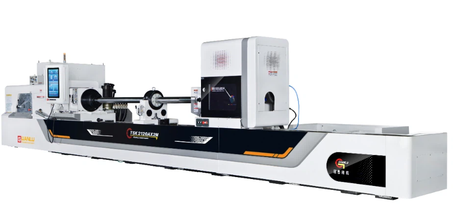
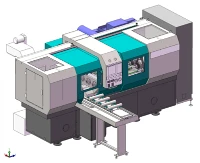
CNC Cavity Deep Hole Machining Machine
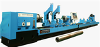
TSK2120ST ×2m CNC cavity deep hole machining machine
Description
TSK2120ST ×2m CNC cavity deep hole machining machine
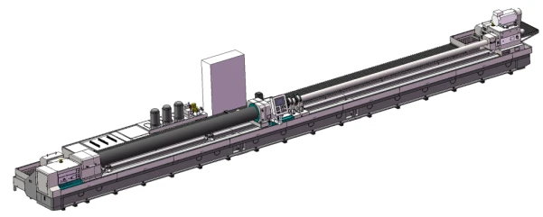
2.TSK2120ST ×2m CNC cavity deep hole machining Tool Functions
This machine is mainly used for boring of deep holes in cavities, but also for drilling and boring of straight holes.
Machine tool processing mode: workpiece fixed, cutter rotation, feed; The workpiece rotates, the tool does not rotate, and the tool is fed; Workpiece rotation, tool rotation, tool feed.
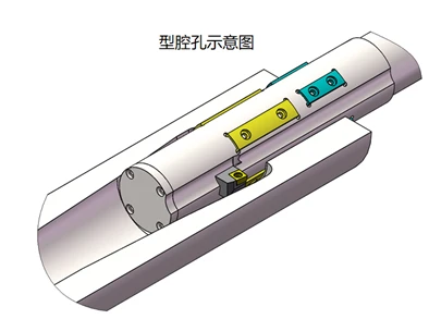
When machining the cavity deep hole, the CNC control system controls the movement of the tool in the X direction (expansion and contraction of the tool) and the movement in the Z direction, and the two axes of the X direction and the Z direction are linked; The tool is guided by the bottom hole of the workpiece, the whole tool retreats in Z direction, and the cutter head moves in X direction at the same time, so as to realize the cavity hole machining.
The cutting oil is supplied through the oil Pressure head, reaches the cutting edge through the gap between the tool rod and the hole wall, cools and lubricates the tool, and the cutting oil carries the chips and is discharged forward into the chip discharge hopper (in the direction of the Headstock)
3. TSK2120ST ×2m CNC cavity deep hole machining machine Tool Overview
3.1 Machine Tool Machining Range
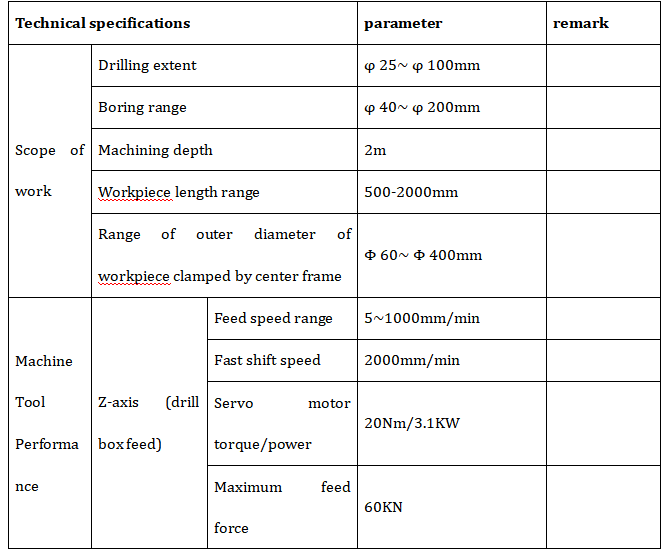
Drilling range: Φ 25~ Φ 100mm
Boring range: Φ 40~ Φ 200mm
Maximum workpiece length/Maximum machining hole depth: 2000mm
3.2 Main structure of machine tool
3.2.1 Main components of machine tools
Bed body, Headstock, oil Pressure head, Boring bar bracket, drilling box, sliding guide rail, ball screw, cooling system, control system, electric box, workpiece bracket, cavity hole processing device, etc.
3.2.2 Machine Tool Control System
Control System: SIEMENS-828D
X-axis: The tool expands and contracts, and the servo motor drives the core rod to move axially through the servo reducer and ball screw.
Z-axis: The structure of the longitudinal feeding motion of the drilling box and the servo motor driving the ball screw.
W axis: The structure in which the oil pressure head servo tightens the workpiece and the servo motor drives the ball screw.
3.2.3 The foundation parts such as box body, bed body and pallet are precision cast with high-quality cast iron. After casting, they are subjected to two aging treatments to eliminate internal stress, stabilize the structure and size, and improve mechanical properties.
3.2.4 Bed
The bed body is cast with resin sand and normalized after casting. The bed body adopts a split structure, which is assembled together using high-strength bolts and positioned with tapered pins.
Adopt double rectangular sliding guide rail, precision grinding, high quenching hardness of guide rail surface.
Ball screws are installed in the bed body to realize X-direction and Z-direction movement.
V-shaped inclined bars are arranged inside the bed body, which has high support strength and is not easy to deform; The outer wall of the bed body directly supports the guide rail, the guide rail can bear large cutting force, the guide rail has good rigidity, and is not easy to deform and shake in the processing process, which is beneficial to improving the processing quality and efficiency of the machine tool.
An oil return groove is cast around the bed body, an oil retaining cover is installed on the oil return groove, and the cutting oil on the bed body is automatically returned to the cooling oil tank.
3.2.5 Headstock
It is used for driving the workpiece to rotate and is fixed at the left end of the bed body.
Manual 3-gear, stepless speed adjustment in gear, using servo spindle motor to drive the spindle to rotate through belt and gearbox, and manual chuck is assembled at the front end of Headstock for clamping workpieces.
Made by precision grinding of gears; The gear tooth surface is treated with high frequency quenching, so that the gear can obtain high strength, high hardness, high wear resistance and high fatigue limit, and can bear relatively large alternating load and impact load.
The external lubricating oil tank is for circulating lubrication of gears and bearings, and a low liquid level alarm device is installed in the oil tank.
A button plate is installed on the headstock body, which has the functions of spindle jog, feed forward, feed backward and emergency stop.
A manual locking device is installed on the spindle of the headstock, and the spindle is locked when the spindle is not required to rotate; Install a detection switch on the locking device, and the main motor will not start when the spindle locking state is detected.

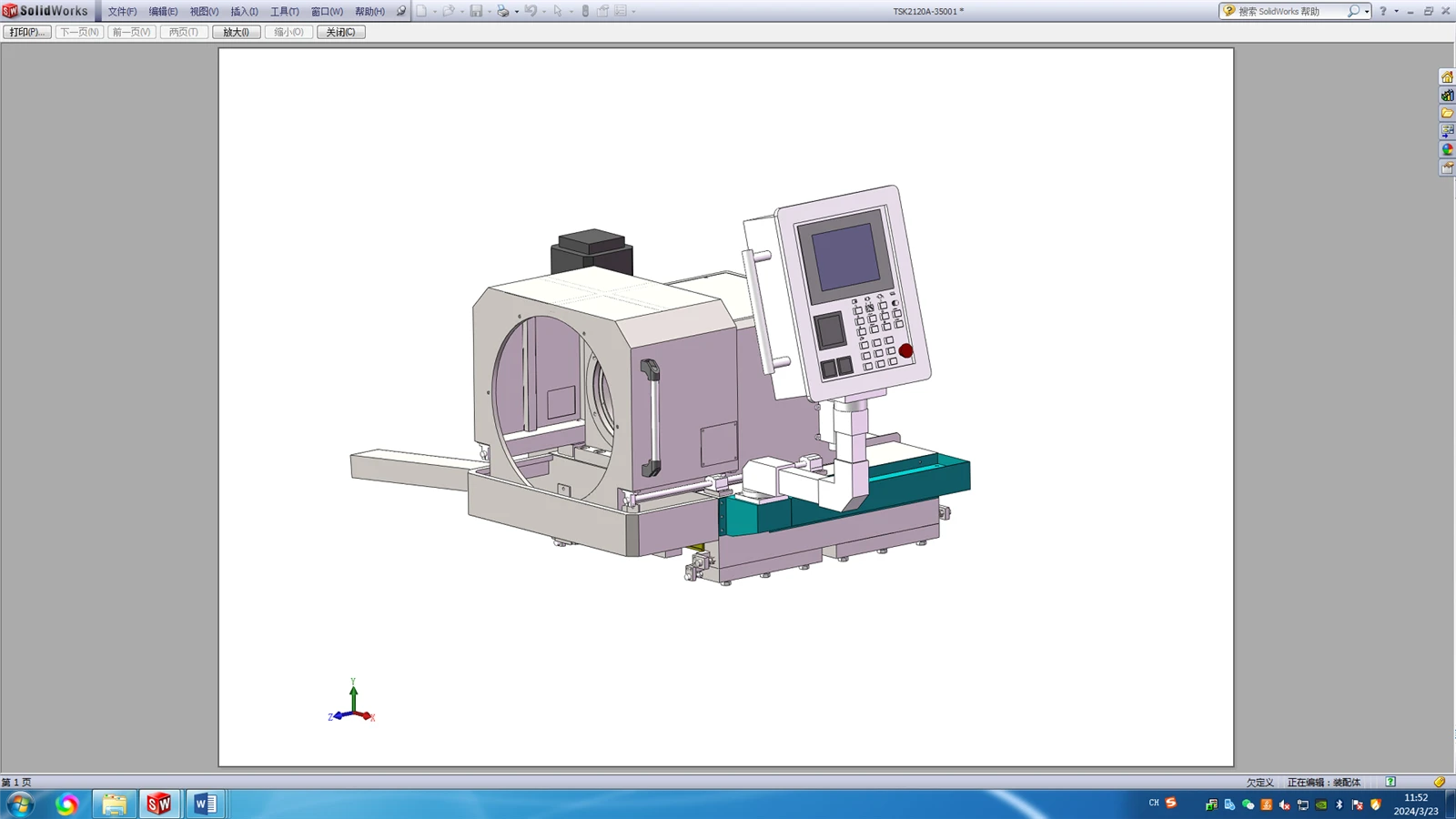
Appearance diagram of headstock
3.2.6 Oil pressure head
Used for tool guidance, tool oil supply, tool bar support.
Servo motor is used to drive its axial movement, which can adapt to the machining of different lengths of workpieces, as well as tightening and loosening of workpieces. The servo motor can operate in torque mode or position mode.
The slewing bearing of the oil dispenser is installed inside the body of the oil pressure head which has good rigidity and high slewing accuracy.
The rotary seal is installed on the outside of the right end of the oil pressure head body for easy maintenance.
A tool bar support sleeve is installed at the right end of the oil pressure head, which is used to support the tool bar.
The left end of the oil pressure head is equipped with a guide sleeve, a conical disc and an oil retaining device. The conical disc is used for positioning the workpiece, and the guide sleeve is used for guiding the cutter.
The oil retaining device has a push-pull structure, and an oil receiving box is installed at the lower part of the oil retaining device so that the cutting oil flows back to the oil tank.
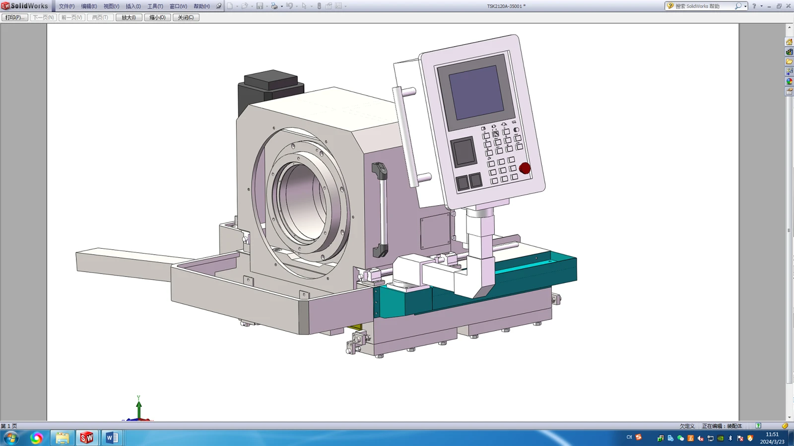
Appearance diagram of oil pressure head
3.2.7 Drilling box
For driving cutter rotation, mounted on feed pallet.
Manual 3-gear, in-gear stepless speed adjustment, using servo spindle motor to drive the spindle to rotate through belt, pulley and gear train.
The left end of the spindle is fitted with a tool holder connecting sleeve for clamping the tool.
A chip discharge hopper is installed at the right end of the spindle for discharging chips.
Made by precision grinding of gears; The gear tooth surface is treated with high frequency quenching, so that the gear can obtain high strength, high hardness, high wear resistance and high fatigue limit, and can bear relatively large alternating load and impact load.
The external lubricating oil tank is for circulating lubrication of gears and bearings, and a low liquid level alarm device is installed in the oil tank.
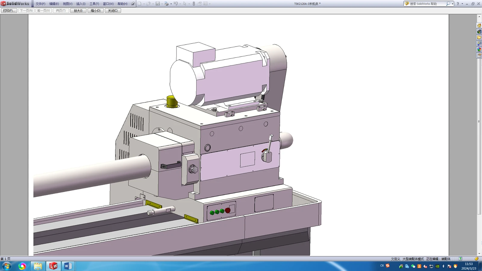
Appearance diagram of drilling box
3.2.8 Toolbar bracket
For supporting a tool bar;
It adopts a high rigidity integral structure with a support sleeve on it, which can absorb the impact and jitter generated in the processing process.
Install the automatic hanging and pulling mechanism, when the tool is withdrawn, the feed pallet can automatically pull the tool bar bracket back to the initial position.
Appearance diagram of tool holder bracket
3.2.9 Cooling System:
It is mainly composed of cooling pump, chip receiving box, oil tank, etc., which provides enough cutting oil for deep hole processing.
Above-ground fuel tank, the fuel tank is fully welded with high-quality steel plate.
Install a telescopic protective cover between the chip receiving boxes on the fuel tank to cover the fuel tank and avoid debris falling into the fuel tank.
The pressure, level, temperature and flow of cutting oil can be displayed digitally on the control station.
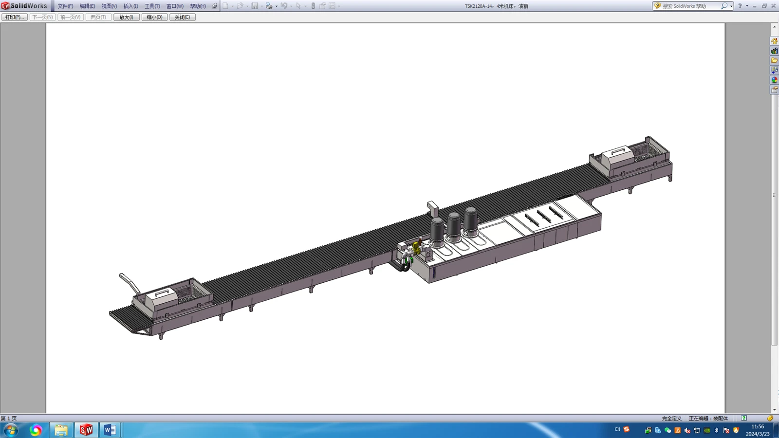
Diagram of cooling system
3.2.10 Feed Pallet
Used to drive the axial movement of the tool.
The automatic lubrication station is used for the time and quantitative lubrication of the sliding rail surface.
A button plate is installed on the pallet, which has the functions of drill pipe box spindle jog, feed forward, feed backward and emergency stop.
3.2.11 Lubrication System
The sliding guide rail surface of the feed pallet is lubricated by automatic lubrication station at time and quantitatively, and has the function of low liquid level alarm.
The bearings and gears of the bedhead box are circularly lubricated by independent external oil tank, and have the function of low liquid level alarm.
The bearings and gears of the drill pipe box are circularly lubricated by independent external oil tank, and have the function of low liquid level alarm.
The oil dispenser support plate and the tool bar support support plate are lubricated by manual lubrication pump.
3.2.12 Workpiece Carrier
For workpiece pre-positioning.
The operator first places the workpiece on the workpiece bracket, and after the workpiece is clamped and positioned, the workpiece leaves the bracket.
The V-shaped frame on the workpiece carrier is manually raised and lowered using the T-shaped screw.
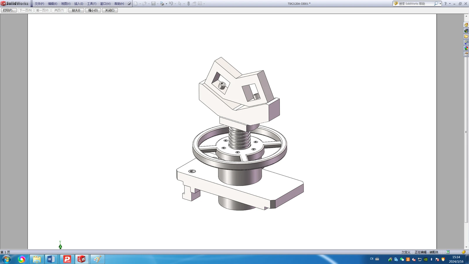
Schematic diagram of workpiece bracket
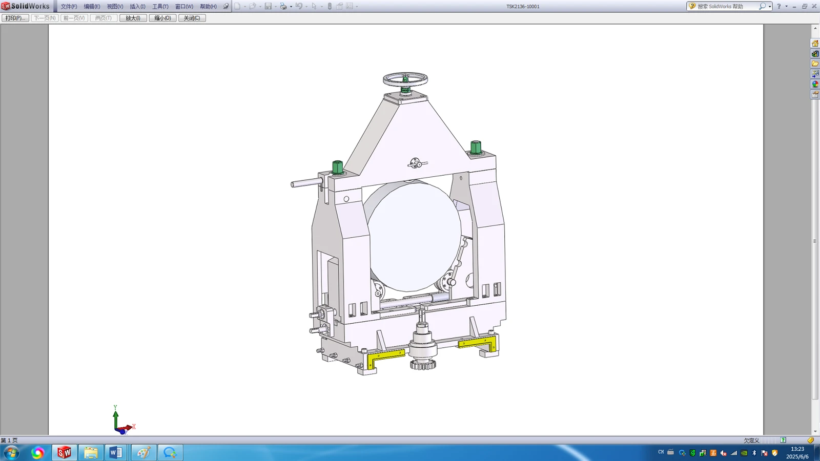
3.2.13 Center frame
For supporting workpieces; Three-point closed center frame structure, two lower rollers and one upper roller; The lower two rollers adjust the lateral position by means of a screw.
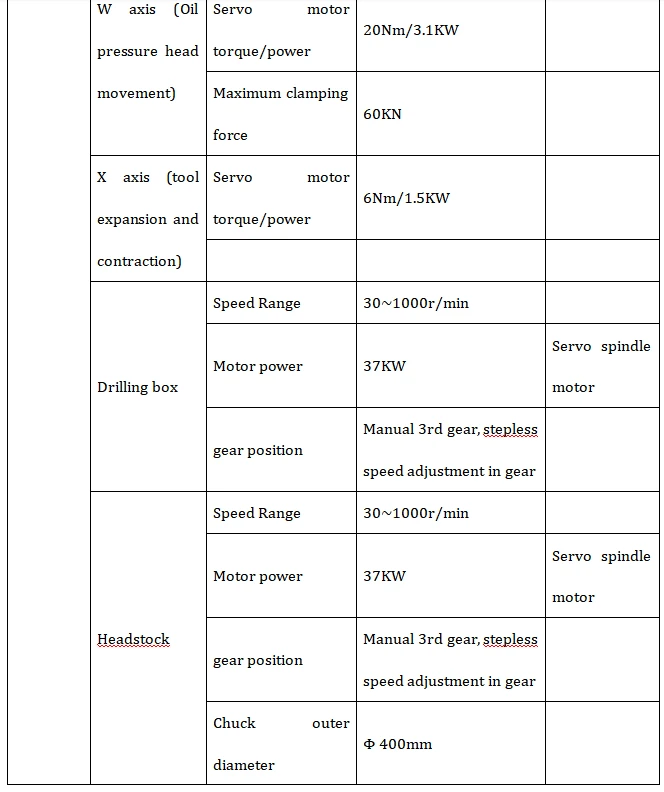
TSK2120ST ×2m CNC cavity deep hole machining machine parameter :
Contact : Lean Lee
Mob :008615153489973
Email ; export@dzguanlu.com
Hot Tags: cnc cavity deep hole machining machine, China, suppliers, manufacturers, factory, customized, price, cheap, company, cost, for sale
You Might Also Like