Latest Products



Contact Us
Add: No.21, D Zone Jingjinluji Industry Park, Xingfu Road, Dezhou City, Shandong, China
Whatsapp/Wechat: +8615165964868
SKYPE: susanleeguobin
Email: dzguanlu@dzguanlu.com
Official webiste: www.dzgljc.com


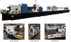
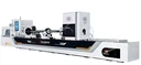
Deep Hole Pull Boring Machine For Cracking Furnace Tubes
Machine application This machine tool is a kind of high efficiency, high precision and high automation deep hole boring and processing equipment. High machining accuracy and surface roughness can be obtained by one continuous feed. This machine is mainly used for deep hole machining of shaft parts. With push boring, pull boring function.
Description
|
Specification |
Parameter |
Remark |
||
|
Working capacity |
Boring hole diameter range |
Φ34~Φ150mm |
||
|
Max. Boring depth |
5m |
|||
|
Workpiece OD range |
Φ50~Φ200mm |
|||
|
Workpiece length range |
1.6m~5m |
|||
|
Machine Features |
Z1 axis (Drill box feeding ) |
Feeding speed range |
5~250mm/min |
|
|
Rapid move speed |
2.7m/min |
|||
|
Servo motor torque/power |
27Nm/4.3KW |
|||
|
Max. Feeding force |
60KN |
|||
|
Z2 axis (Oil pressure head movement) |
Rapid move speed |
2.7m/min |
||
|
Servo motor torque/power |
20Nm/3.1KW |
|||
|
Drill box |
Gear quantity |
3pcs |
Manual shift |
|
|
Rotary speed range |
30-600r/min |
|||
|
Motor power |
74KW |
Servo spindle motor |
||
|
Others |
Height from machine spindle center to guide rail top surface |
450mm |
||
|
Height from machine spindle center to floor |
1100mm |
|||
|
Machine general power |
100KW |
|||
|
Machine loading weight |
400kg |
|||
|
Machine floor size |
17.1m×2. 1m |
|||
|
Boring bar auxiliary length |
2.2m |
|||
|
Coolant system |
Oil supply pressure |
Pull boring:5-8bar; Push boring: 10-20bar |
||
|
Pump group |
100L/min ,2groups ,7.5KW
|
|||
|
100L/min,1group,7.5KW Variable frequency pump |
|||
|
Equipped with 180 μm mesh suction filter |
|||
|
Oil tank volume |
2400L |
||
Machine structures:
Machine bed
The structure of the bed is closed on three sides and has a reasonable
arrangement of reinforced plates, so its rigidity meets the needs of high-speed cutting. The double rectangular sliding guide rail is machined on the bed body, and is treated by precision grinding and medium frequency quenching. The
rack in the middle of the bed body (modulus 6mm) is used for the movement of the oil feeder and the feed plate.

Figure 6. Cross-section of the bed
Feeding system
Used to drive the tool to do feed movement.
The guide rail of the feed system adopts double rectangular sliding guide rail.
The servo motor drives the rack and pinion mechanism after decelerating through the gearbox, so as to realize the movement of the Z axis and the stepless speed regulation of the Z axis movement speed. The guide rail clearance can be adjusted manually with inserts on the bracket and handle plate.

Figure 7. Feed plate drawing
Oil pressure head
The right end of the cone and guide sleeve are installed to guide the drill, seal and supply oil; The rigidity of the drill pipe can be improved by assembling the drill pipe support sleeve at its left end to provide support for the drill pipe.
The oil receiver bracket is equipped with a servo drive mechanism to control the oil receiver to tighten or loosen the workpiece; The driving mechanism is composed of a servo motor and a gearbox. The oil feeder is moved axially through the rack on the bed. The jacking force of the oil feeder on the workpiece can be set on the operating panel, and the size of the jacking force depends on the actual processing situation.
When machining the workpiece with different apertures, it is necessary to replace the matching guide sleeve and support sleeve. And after the machine tool works for a period of time, the inner hole of the guide sleeve will have a certain degree of wear, and when it can not meet the specific requirements of the precision of the workpiece, it is necessary to replace the new guide sleeve.

Figure 8. Oil pressure head
Coolant system
The role of the cutting coolant: to cool the cutting edge of the tool, to lubricate the tool and its support pad, and to flush the chip.
The cutting coolant is supplied by a cooling pump station mounted on the cooling tank at the back of the bed, and the cutting coolant is pumped through the pump, transported directly to the oil receiver or tailstock, and then transported to the cutting area, and the cutting fluid with chips is discharged into the chip receiving device through the chip discharge channel.
When drawing and boring, oil is supplied through the oil feeder, and the chip is removed from the tail seat. When pushing boring, oil is supplied through the tail seat, and chip is removed from the front end of the oil receiver.
Cooling pump station: 1 group of variable frequency pumps, 2 groups of quantitative pumps, the maximum flow of each group of pumps 100L/min.
The pressure of the cooling system is adjusted by the high-pressure relief valve, and the specific pressure value is displayed by the pressure gauge.
There are two oil circuits on the integrated block where the relief valve is
located, which lead to the oil receiver and the tail seat; When pushing boring, open the oil circuit leading to the tailstock; When pulling the boring, open the oil line to the oil feeder.
The fuel tank volume of the machine tool is 2400 liters, and the deep hole special cutting oil is used. The tank is cleaned every 2-4 months.
The filter of the oil tank and the chip removal machine shall be cleaned once per shift.

Figure 9. Coolant system
Lubrication system
The slide of the feed plate on the guide rail of the machine tool is lubricated by the automatic lubrication station, and the schematic diagram is shown in Figure 10.

Figure 10. Schematic diagram of automatic lubrication station
After the motor of the automatic lubrication station starts, the oil pump works to supply oil, the oil pressure is adjusted by the relief valve, and the oil flows through the hydraulic direction change valve (shown as the oil return position) to the required lubrication points
The fuel tank is also equipped with the lowest oil level alarm device, when the oil level drops to the lowest oil level, the corresponding indicator
light on the central control station is lit, at this time to inform the operator must refuel the pump station, so the automatic lubrication system has a high degree of automation.
In general, the automatic lubrication station is refueled twice a week.
The gear and main shaft bearings of the drill pipe box are automatically lubricated by an independent lubricating oil box, as shown in Figure 11. The oil tank volume is 30 liters, and the high-speed mechanical oil of No. 32 or lubricating oil of this nature is used.

Figure 11.Drill box lubrication drawing
The feed plate is equipped with gears, bearings, etc., and it is lubricated with No. 32 high-speed mechanical oil or lubricating oil equivalent to this nature. The fuel tank volume is 10 liters.
Figure 12.Drawing for lubrication of bracket of drill box
The oil receiver bracket is equipped with gears, bearings, etc., and it is lubricated with No. 32 high-speed mechanical oil or lubricating oil equivalent to this nature. The fuel tank volume is 10 liters.
Figure 13.Grease drawing for receiver plate
Turboworm, gear, bearing, etc. are installed inside the tailstock bracket, which is lubricated with No. 32 high-speed mechanical oil or lubricating oil equivalent to this property. The fuel tank volume is 15 liters.

Figure 14. Drawing for lubrication of tailstock plate
Oil receiver bracket, drill pipe box bracket, drill pipe box, tailstock bracket board oil tank total volume 65 liters.
Tailstock
When drawing boring, it is used for workpiece positioning and chip removal; When pushing boring, it is used for workpiece positioning and oil supply.
The hydraulic motor drives the rack and pinion through the decelerating mechanism to realize the axial movement of the tail seat.
The right end is fitted with a cone, and the left end and upper cover plate can be opened.
Figure 15. Tailstock
Center rest
Used to clamp the workpiece and fix the workpiece.
The hydraulic motor controls the rotation of the ball screw of the positive
and negative φ63 specifications, which drives the gripper to move radially at the same time to realize the clamping and loosening of the workpiece.
The manual gear is installed on the side of the workpiece bracket, and the movement of the workpiece bracket on the bed can be realized by using the rack on the bed body. It is fixed on the guide rail of the bed body by a manual locking block.

Figure 16. Center rest
Boring bar support rest
Used to support the tool bar.
It can move on the guide rail of the bed body. The high rigidity of the integral structure, which is equipped with support sleeve, can absorb the impact of the processing process, shake and so on.
The tool bar bracket is installed with a hanging mechanism, and the hole is automatically pulled back to the original position after machining.

Figure 17.Boring bar support rest
Drill box
Used to drive tool rotation; Manual 3 speed, stepless speed control; Speed range 50-600r/min; The front end of the spindle is equipped with a tool holder connecting sleeve (the user's tool holder connecting sleeve can be installed, the user provided drawings are not clear, provide clear drawings) for clamping tools. After the main motor is decelerated by the synchronous belt, synchronous belt wheel and gear system, it drives the spindle to rotate.
Gear precision grinding processing; Gear tooth surface after high-frequency quenching treatment, tooth surface hardness HRC48-52, so that the gear can obtain high strength, high hardness, high wear resistance and high fatigue limit, can withstand relatively large alternating load, impact load.
In order to improve the life of gears and bearings, lubricating oil circulation lubrication is used.

Figure 18.Drill box
Workpiece support rest
Install on the center frame tray.
Adjust the height manually according to different workpiece specifications. In the process of machine tool processing, the hydraulic system controls the lifting

Figure 19.Workpiece support rest
Hydraulic system
It is used to control the axial movement of the tailstock and the clamping or loosening movement of the center frame on the workpiece.

Hot Tags: deep hole pull boring machine for cracking furnace tubes, China, suppliers, manufacturers, factory, customized, price, cheap, company, cost, for sale
You Might Also Like