
Latest Products


Contact Us
Add: No.21, D Zone Jingjinluji Industry Park, Xingfu Road, Dezhou City, Shandong, China
Whatsapp/Wechat: +8615165964868
SKYPE: susanleeguobin
Email: dzguanlu@dzguanlu.com
Official webiste: www.dzgljc.com

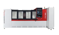
TSK2130DZ CNC Deep Hole Drilling & Boring Machine
Machine Functions Operating modes of the machine: Workpiece rotation, stationary tool with tool feed; Workpiece rotation, tool rotation with tool feed. Drilling: BTA drilling method. Cutting oil is supplied to the tool through the oil feeder and the clearance between the boring bar and the hole wall. Chips are discharged through the inner bore of the boring bar. Boring: Cutting oil is delivered to the tool via the oil feeder and the clearance between the boring bar and the hole wall. Chips are discharged through the bottom hole of the workpiece. The tool moves towards the headstock during machining. Trepaning: Internal oil supply and external chip removal. Cutting oil is fed to the tool through the inner bore of the boring bar, and chips are discharged through the gap between the outer surface of the boring bar and the machined hole.
Description
1.Machine Overview
1.1 Machining Range
Drilling range: Φ80~Φ200 mm
Boring range: Φ80~Φ300 mm
Trepaning range: Φ200~Φ300 mm
Workpiece outer diameter range: Φ200~Φ600 mm
Workpiece length range: 500~2000 mm
1.2 Machine Functions
Machine operating modes: Workpiece rotation, stationary tool with tool feed; Workpiece rotation, tool rotation with tool feed.
Drilling: Adopt BTA drilling method. Cutting oil is supplied to the tool through the oil feeder and the clearance between the boring bar and hole wall, and chips are discharged through the inner bore of the boring bar.
Boring: Cutting oil is delivered to the tool via the oil feeder and the clearance between the boring bar and hole wall. Chips are discharged through the bottom hole of the workpiece. The tool moves towards the headstock during machining.
Trepaning: Internal oil supply and external chip removal. Cutting oil is fed to the tool through the inner bore of the boring bar, and chips are discharged through the gap between the outer surface of the boring bar and the machined hole.
1.3 Main Machine Structure
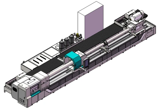
1.3.1 Main Machine Components
Bed, headstock, oil feeder, boring bar support, drill headstock, sliding guideways, rack and pinion, cooling system, control system, electrical cabinet, workpiece supports, etc.
1.3.2 Workpiece Clamping
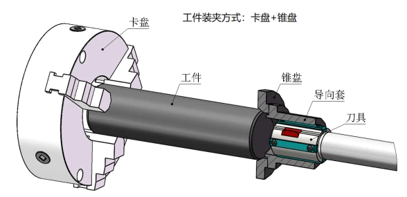
1.3.2.1 For Drilling and Boring Operations
One end of the workpiece is clamped by the manual three-jaw chuck mounted on the headstock, and the other end of the workpiece is automatically tightened by the taper disc of the oil feeder.
1.3.2.2 For Trepaning Operations
One end of the workpiece is clamped by the manual three-jaw chuck on the headstock, and the other end is supported by the steady rest.
1.3.3 Machine Control System
Control system: PLC Z-axis: Longitudinal feed motion of the drill headstock. The servo motor drives the rack-and-pinion mechanism via a reduction unit. X-axis: Servo-driven tightening of the workpiece by the oil feeder. The servo motor drives the rack-and-pinion mechanism via a reduction unit.
1.3.4 Basic Components
The cabinet, bed, slide plate and other basic parts are precisely cast from high-quality cast iron. After casting, they undergo two stress relief treatments to eliminate internal stress, stabilize structure and dimensions, and improve mechanical properties.
1.3.5 Bed
The bed is produced by resin sand casting followed by normalizing treatment. It adopts a split structure assembled with high-strength bolts and positioned by taper pins. Equipped with double rectangular sliding guideways finished by precision grinding; the guide surfaces feature high hardness after quenching. An inclined rack is installed inside the bed for tool feed transmission. The rack is precision machined and quenched. The machine features heavy load capacity, high rigidity and stable transmission. V-shaped inclined ribs are arranged inside the bed to provide strong support and resist deformation. The outer wall of the bed directly supports the guideways, enabling the guideways to withstand heavy cutting forces with excellent rigidity. Deformation and vibration during machining are minimized, which helps improve machining quality and efficiency. Oil return channels are cast around the bed with oil shields mounted on them. Cutting oil on the bed flows back to the cooling tank automatically.
1.3.6 Headstock
It is mounted on the left end of the bed to drive workpiece rotation. The spindle features stepless speed regulation. A servo spindle motor drives the spindle via belts and gearbox. A manual chuck is fitted on the front end of the headstock for workpiece clamping. Gears are precision ground, and their tooth surfaces are high-frequency quenched to achieve high strength, hardness, wear resistance and fatigue limit, capable of sustaining large alternating and impact loads. An external lubrication tank provides circulating lubrication for gears and bearings, equipped with a low-level alarm device inside the tank. A push-button panel is mounted on the headstock housing, which supports spindle jogging, feed forward, feed backward and emergency stop functions.
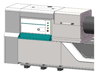
1.3.7 Oil Feeder
It serves for tool guiding, cutting oil supply and boring bar support.
It is driven by a servo motor for axial movement to accommodate workpieces of different lengths, and to tighten and release the workpiece. The servo motor can operate in torque mode or position mode.
The slewing bearing is installed inside the oil feeder body, featuring high rigidity and high rotational accuracy.
Rotary seals are mounted externally on the right end of the oil feeder body for easy maintenance.
A boring bar support sleeve is fitted on the right side of the oil feeder to support the boring bar.
The left side of the oil feeder is equipped with a guide sleeve, taper disc and oil retaining device. The taper disc is used for workpiece positioning, while the guide sleeve provides guidance for the tool.
The oil retaining device adopts a push-pull structure. An oil collecting tray is arranged beneath the oil retaining device to channel cutting oil back to the oil tank.
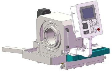
1.3.8 Drill Headstock
It is used to drive tool rotation and mounted on the feed slide.
The spindle realizes stepless speed regulation. A servo spindle motor drives the spindle via belts, pulleys and gear train.
A tool shank adapter is fitted on the left end of the spindle for tool clamping.
A chip chute is installed on the right end of the spindle for chip evacuation.
All gears are precision ground. The gear tooth surfaces are treated by high-frequency quenching to achieve high strength, high hardness, excellent wear resistance and high fatigue limit, enabling them to withstand heavy alternating loads and impact loads.
An external lubrication tank provides circulating lubrication for gears and bearings, and a low oil level alarm device is equipped inside the tank.
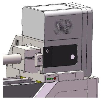
1.3.9 Boring Bar Support
It is used to support the boring bar. It adopts a high-rigidity monolithic structure fitted with support sleeves, which can absorb shocks, vibrations and other disturbances generated during machining. An automatic pull-back mechanism is equipped. During tool retraction, the feed slide can automatically pull the boring bar support back to its home position.
1.3.10 Cooling System
It mainly consists of cooling pumps, chip collecting box, oil tank and other components to supply sufficient cutting oil for deep hole machining. This is an above-ground oil tank fabricated with full welding of high-quality steel plates. A chain-plate automatic chip conveyor is mounted on the oil tank. The pressure, liquid level, temperature and flow rate of cutting oil can be digitally displayed on the operator station.
1.3.11 Feed Slide
It is used to drive the tool for axial movement. The servo motor drives a double gear arrangement via a reducer; the rack is a helical rack with module 6. An automatic lubrication unit provides timed and quantitative lubrication for the sliding guide surfaces. A push-button panel is mounted on the slide, featuring jog operation of the drill headstock spindle, feed forward, feed backward and emergency stop functions.
Double gear drive: One servo motor transmits power to two drive gears through a gear train, which drives the tool forward and backward via the rack fitted on the bed.
1.3.12 Lubrication System
The sliding guide surfaces of the feed slide are lubricated by an automatic lubrication unit with timed and quantitative oil supply, equipped with a low oil level alarm. Bearings and gears of the headstock adopt circulating lubrication by an independent external oil tank with low oil level alarm. Bearings and gears of the drill headstock adopt circulating lubrication by an independent external oil tank with low oil level alarm. The oil feeder slide and boring bar support slide are lubricated by a manual lubrication pump.
1.3.13 Workpiece Support
It is applied for pre-positioning of workpieces. The operator places the workpiece on the workpiece support first. After the workpiece is clamped and positioned, it separates from the support. The V-block on the workpiece support is manually lifted and lowered by a T-type lead screw.
1.3.14 Steady Rest
It serves to support the workpiece. It adopts a three-point closed steady rest structure with two rollers at the bottom and one roller on the top. The transverse position of the two bottom rollers can be adjusted via lead screws.
2. Main Machine Parameters
Technical Specifications
Machining Range
Drilling range: Φ80~Φ200 mm
Boring range: Φ80~Φ300 mm
Trepaning range: Φ200~Φ300 mm
Maximum machining depth: 8 m
Workpiece length range: 0.5~8 m
Workpiece outer diameter range: Φ200~Φ600 mm
Machine Performance
Z-axis (Drill headstock feed) Feed speed range: 5~1000 mm/min
Rapid traverse speed: 2000 mm/min
Servo motor torque / power: 48 Nm / 7.5 kW
Maximum feed force: 80 kN
X-axis (Oil feeder movement) Rapid traverse speed: 2000 mm/min
Servo motor torque / power: 27 Nm / 4.3 kW
Maximum tightening force: 60 kN
Drill headstock
Speed range: 30~200 r/min, stepless speed regulation
Motor power: 75 kW, servo spindle motor
Spindle front taper bore: Metric 140
Spindle through hole: Φ120 mm
Headstock Speed range: 30~200 r/min
Motor power: 75 kW, servo spindle motor
Spindle front taper bore: Metric 140
Spindle through hole: Φ120 mm
Other Parameters
Total installed power of machine: 192 kW
Maximum load capacity of machine: 5 tons
Machine footprint: 22 m × 3.3 m
Guideway width: 690 mm
Clamping range of steady rest: Φ200~Φ600 mm
Height from spindle center to guideway surface: 500 mm
Chuck fitted on headstock: Φ630 mm, manual three-jaw self-centering chuck
Cooling System
Maximum pressure: 2.5 MPa
Maximum flow rate: 400 L/min
Oil tank capacity: approx. 6300 L
4.Contact Me:
Email:sale@dzguanlu.com
Whatsapp:+8613853423246
Hot Tags: tsk2130dz cnc deep hole drilling & boring machine, China, suppliers, manufacturers, factory, customized, price, cheap, company, cost, for sale
You Might Also Like


