
Latest Products


Contact Us
Add: No.21, D Zone Jingjinluji Industry Park, Xingfu Road, Dezhou City, Shandong, China
Whatsapp/Wechat: +8615165964868
SKYPE: susanleeguobin
Email: dzguanlu@dzguanlu.com
Official webiste: www.dzgljc.com

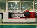
CNC Broaching Machine
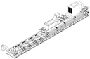
1. Machine appearance sketch: 2. Overview of machine: 2.1 Machine application Grooving machining of coaxial holes for cylindrical workpieces. The tool can be expanded and contracted (X axis), the workpiece can be indexed and rotated (C axis), and the tool can reciprocate (Z axis); The broaching...
Description
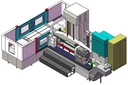
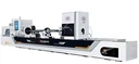
1. Machine appearance sketch:


2. Overview of machine:
2.1 Machine application
Grooving machining of coaxial holes for cylindrical workpieces.
The tool can be expanded and contracted (X axis), the workpiece can be indexed and rotated (C axis), and the tool can reciprocate (Z axis); The broaching of the inner hole is completed by using the expansion and contraction cutter and the two-axis linkage of Z-axis and
C-axis.
A through-type headstock is adopted, and chucks are installed at both ends of the headstock; Hydraulic center rest and headstock chucks combination for clamping workpieces.
3. Main parameters of machine :
|
Technical specifications |
Parameter |
Remark |
||
|
Working capacity |
Hole diameter range |
Φ20~Φ50mm |
||
|
Workpiece length range |
1000-3000mm |
|||
|
Max. machining depth |
3000mm |
|||
|
Workpiece OD range |
Φ30~Φ100mm |
|||
|
Machine performance |
Z-axis (tool feed) |
Feed speed range |
5 ~ 500mm/min |
|
|
Fast moving speed |
8000mm/min |
|||
|
Servo motor |
48Nm/7.7 KW |
|||
|
Linear guide rail specifications |
45 |
|||
|
Linear guide form |
Roller heavy-duty linear guide |
|||
|
Ball screw for transmission |
φ 80 × 20 mm |
|||
|
Ball screw nut |
Double nut |
|||
|
Max. feed force |
60KN |
|||
|
U-axis (oil |
Fast moving speed |
8000mm/min |
||
|
pressure head movement) |
Servo motor |
16Nm/2.6 KW |
||
|
Linear guide rail specifications |
45 |
|||
|
Linear guide form |
Roller heavy-duty linear guide |
|||
|
Ball screw for transmission |
φ 50 × 10 mm |
|||
|
Ball screw nut |
Double nut |
|||
|
Max. tightening force |
30KN |
|||
|
Headstock (workpiece indexing) |
Max. rotation speed |
10r/min |
Stepless |
|
|
Servo motor |
16Nm/2.6 KW × 2 |
|||
|
Indexing accuracy |
30″ |
|||
|
Chuck Specifications |
φ 400 mm × 2 Manual three-jaw self-centering chuck |
|||
|
Chuck inner bore, spindle inner bore |
φ130mm |
|||
|
Cooling system |
Max. pressure |
5MPa |
Adjustable |
|
|
Max. flow rate |
100L/min |
Adjustable |
||
|
Oil pump/motor |
7.5 KW variable frequency gear pump, 1 set |
|||
|
Tank volume |
1000L |
|||
|
Filtering form |
Drum paper filter |
|||
|
Filtration capacity |
200L/min |
|||
|
Filtration accuracy |
20 μm |
|||
|
Oil chiller cooling capacity |
5KW |
|||
|
other |
Total machine power (approx.) |
26KW |
||
|
Total machine weight (approx.) |
14T |
|||
|
Machine footprint |
9.5m×3.5m |
|||
4. Machine structure description:
4.1 Tool expansion and contraction
The cutter expansion and contraction device installed on the reciprocating carriage pushes the inner core rod of the tool bar to move axially, the core rod is installed on the cutter body, and the inclined surface on the cutter body drives the cutter to move radially.
4.2 Workpiece clamping
The workpiece passes through the inner hole of the headstock spindle → chucks at both ends of the headstock spindle clamp the workpiece → hydraulic center rest clamps the workpiece → oil pressure head tighten the left end of the workpiece.
4.3 Oil circuit
The cutting oil enters through the oil pressure head, carries the chips through the basic hole of the workpiece, enters the chips removal bucket, and then discharges into the chips
conveyor.
4.4 Reciprocating movement of the cutter
The servo motor drives the ball screw through the servo reducer to realize the reciprocating motion of the cutter.
The nut on the ball screw is a double nut structure, which is lubricated regularly and quantitatively by automatic lubrication station.
Both ends of the screw are installed with special bearings for the screw, which adopt a bearing structure with one end fixed and one end stretched.
4.5 Support rest of tool bar
The support sleeve installed on the tool bar support rest is used to support the tool bar to enhance the rigidity of the tool bar.
The tool bar support rest is mounted on two linear guide sliders and can automatically adjust the spacing with the movement of the drill box.

Appearance diagram of tool bar support rest

Follow-up diagram of tool bar support rest
4.6 Indexing of workpiece
The workpiece is driven by the headstock to rotate and index, and the rotating speed of the workpiece is stepless and adjustable.
Two servo motors drive the spindle to index and rotate with C-axis function.
The headstock is fixed on the bed body of the machine, and manual three-jaw self-centering chucks are installed at both ends of the spindle.
Through-type headstock, the workpiece passes through the inner hole of the spindle, and the chucks at both ends is used to clamp the workpiece.

Sketch of headstock appearance
4.7 Cooling system
It consists of magnetic chips conveyor, circulating pump, drum paper filter, oil chiller, pump group, liquid level sensor, flow sensor, pressure sensor, temperature sensor and oil tank.
The pump unit is driven by a variable frequency motor, and the output flow rate of the pump is adjusted by adjusting the speed of the motor. The oil outlet of the pump is equipped with a manual relief valve to adjust the output pressure of the pump.
Various sensors are installed on the cooling system, and the liquid level, oil temperature, flow rate and pressure are displayed on the instrument.
Cooling system schematic diagram
4.8 Control system
CNC system: SIEMENS-828D
Mainly used for control: Cutter reciprocating movement, workpiece indexing rotation, cooling system, lubrication system, oil pressure head movement, hydraulic center rest, C-axis and Z-axis two-axis linkage, etc.
4.9 Lubrication system
The linear guide rail sliders of oil pressure head and reciprocating carriage, screw nut and headstock spindle are lubricated regularly and quantitatively by automatic lubrication station.
4.10 Machine safety guard (optional)
Can be designed and manufactured according to user requirements
4.11 Oil pressure head
It is used for supplying cutting oil to the cutter and can move axially under the control of CNC system;
When loading and unloading workpieces, the oil pressure head moves to the left end of the bed to give up space and facilitate loading and unloading workpieces.
During processing, the oil pressure head is tightly tightening on the left end of the workpiece, which plays the role of oil sealing and workpiece positioning.
5. Standard parts of machine
|
No. |
Name |
QTY |
|
1 |
Bed body |
1 set |
|
2 |
Reciprocating carriage |
1 set |
|
3 |
Headstock |
1 set |
|
4 |
Oil pressure head |
1 set |
|
5 |
Workpiece carrier |
2 sets |
|
6 |
Tool bar support rest |
2 sets |
|
7 |
Cooling system |
1 set |
|
8 |
Cutter feed system |
1 set |
|
9 |
Lubrication system |
1 set |
|
10 |
SIEMENS-828D Control System |
1 set |
|
11 |
Electric box (with air conditioner) |
1 set |
|
12 |
User Manual |
1 set |
|
13 |
Hydraulic center rest |
1 set |
|
14 |
Hydraulic station |
1 set |
|
15 |
Chip removal bucket |
1 set |
|
16 |
Cutter expansion and contraction device |
1 set |
7. Machine main configurations:
Item Name Manufacturer
CNC system
Servo feed motor
Spindle bearing for headstock
Linear guide rail
Ball screw
Chuck Zhejiang YUAN brand
Hydraulic center rest Yantai
9. Machine protection measures:
Machine lubrication oil deficiency protection
Cooling system level and pressure protection
Feed motor load protection
Cooling pump motor fault alarm
Limit protection
10. Documents provided:
Mechanical user manual 1set
Electrical user manual 1set
CNC program backup 1set
Machine appearance sketch and foundation drawing 1set
Packing list 1set
Certificate of Conformity 1set
6. Machine Optional parts:
Cutter, auxiliary tools, cutting oil
Hot Tags: cnc broaching machine, China, suppliers, manufacturers, factory, customized, price, cheap, company, cost, for sale
You Might Also Like


