
Latest Products


Contact Us
Add: No.21, D Zone Jingjinluji Industry Park, Xingfu Road, Dezhou City, Shandong, China
Whatsapp/Wechat: +8615165964868
SKYPE: susanleeguobin
Email: dzguanlu@dzguanlu.com
Official webiste: www.dzgljc.com

ZSK2108 CNC Deep Hole Drilling Machine
The overall design and performance parameters described above are specifically realised in the ZSK2108 CNC deep hole drilling machine . T his model integrates the BTA drilling method, rigid bed construction, and Siemens-controlled servo drives into a compact production unit. The ZSK2108 CNC deep...
Description
The overall design and performance parameters described above are specifically realised in the ZSK2108 CNC deep hole drilling machine. This model integrates the BTA drilling method, rigid bed construction, and Siemens-controlled servo drives into a compact production unit. The ZSK2108 CNC deep hole drilling machine is particularly suited for batch processing of shafts and tubular components within the φ16–φ80 mm range. Its oil-pressure head and drill box configurations are tailored to the ZSK2108 CNC deep hole drilling machine's duty cycle, ensuring stable chip removal and thermal balance. Moreover, the cooling and filtration system of the ZSK2108 CNC deep hole drilling machine is engineered to support continuous operation, while the manual adjustment features on the bed and bracket add flexibility for setup changes-making the ZSK2108 CNC deep hole drilling machine a reliable choice for medium-depth bore applications. All structural and control features converge to define the ZSK2108 CNC deep hole drilling machine as a robust, service-friendly solution for precision deep-hole machining.
2. Machine Tool Overview
2.1 Processing Method
This machine adopts the BTA (Boring and Trepanning Association) deep-hole drilling process. During operation, cutting oil is delivered to the tool through the annular gap formed between the oil-pressure head, the tool bar, and the bore wall. The oil then carries the generated chips back through the internal passage of the tool bar and discharges them out of the system. The cutting action is achieved by the relative rotation between the tool and the workpiece.
2.2 Machining Range
BTA drilling diameter range: φ16 – φ80 mm
Maximum drilling depth: 1000 mm
Maximum workpiece length: 1000 mm
2.3 Main Structure of the Machine Tool
2.3.1 Major Components
The machine consists of the bed body, headstock, oil-pressure head, tool holder, drill box, cooling system, control panel, electrical cabinet, workpiece support brackets, and other auxiliary units.
2.3.2 Workpiece Clamping
One end of the workpiece is clamped by the manual three-jaw chuck mounted on the headstock, while the other end is automatically secured by the cone-shaped clamping mechanism of the oil-pressure head. A clamping layout diagram is provided for reference.
2.3.3 Control System
The machine is equipped with a SIEMENS-808D CNC control unit. The Z-axis feed motion of the drill pipe box is driven by a servo motor via a reduction gearbox and a rack-and-pinion mechanism. The control system governs workpiece rotation, tool rotation, tool feed, coolant supply, and other operational parameters.
2.3.4 Base Structural Parts
Key foundation components-such as the gearbox housing, bed, and pallets-are precision-cast from high-quality cast iron. After casting, these parts undergo two aging treatments to eliminate residual internal stresses, ensuring dimensional stability and enhanced mechanical properties over the long term.
2.3.5 Bed Structure
The bed is resin-sand cast and normalized after solidification. It features a double rectangular sliding guideway for the tool bed, which is precision-ground and induction-hardened to achieve high surface hardness. A ball screw is housed inside the tool bed body for feed transmission, while a rack mounted on the side allows manual adjustment of the tool bar holder's position.
For the workpiece bed, a heavy-duty ball-type linear guide rail is installed, along with a T-slotted worktable. The headstock can be manually repositioned along this rail for quick and convenient setup. Inside the bed, V-shaped inclined ribs provide high support rigidity and resistance to deformation. The outer wall directly supports the guide rail, enabling it to withstand substantial cutting forces with good stiffness, minimising vibration and deflection during processing-thereby improving both machining quality and efficiency.
An integral oil return channel is cast around the bed, covered with an oil-deflecting shield, allowing cutting fluid to flow back automatically into the cooling tank.
2.3.6 Headstock
The headstock drives workpiece rotation and is mounted on the linear guide rail of the workpiece bed. The main motor transmits power through a belt and reduction gearbox, delivering a fixed rotational speed. At the front end, a manual three-jaw chuck and an oil-sealing device are fitted for workpiece clamping. The entire headstock can be moved axially by hand along the guide rail and locked in place with a clamping block once positioned. A control panel on the headstock body provides functions including spindle jog, spindle clamping/unclamping, and emergency stop.
2.3.7 Oil-Pressure Head
This unit serves three purposes: tool guidance, cutting oil supply, and tool bar support. It is installed in the middle section of the bed and moves axially under hydraulic control to tighten or release the workpiece. A support sleeve at the right end holds the tool bar, while the left end carries a guide sleeve and a conical disc-the disc locates the workpiece, and the guide sleeve directs the cutter during entry.
2.3.8 Drill Box
Mounted on the feed pallet, the drill box drives tool rotation. A servo spindle motor, connected via belt and pulleys, provides infinitely variable speed control. The left end of the spindle is fitted with a tool-holder connecting sleeve for cutter mounting, and a chip-discharge hopper is installed at the right end. The main motor is positioned at the front, with its tail end facing away from the tool sleeve-this layout reduces the risk of oil ingress into the motor, extends motor service life, and facilitates tool changes. An operating panel on the box offers spindle inching, forward/reverse rotation, and emergency stop functions.
2.3.9 Tool Bar Bracket
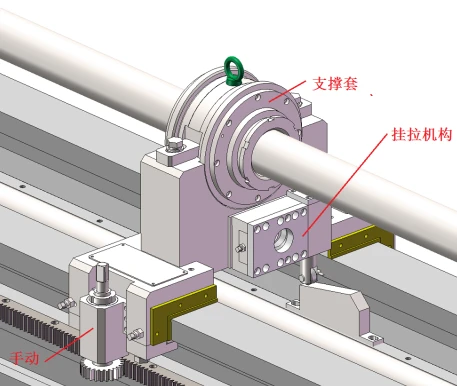
Designed as a high-rigidity one-piece structure with an integral support sleeve, this bracket absorbs impact and dampens vibration during cutting. An automatic hook-and-pull mechanism enables the feed pallet to retract the bracket to its initial position when the tool is withdrawn. Additionally, a manual adjustment gear on the bracket allows operators to reposition it along the bed as needed.
2.3.10 Cooling System
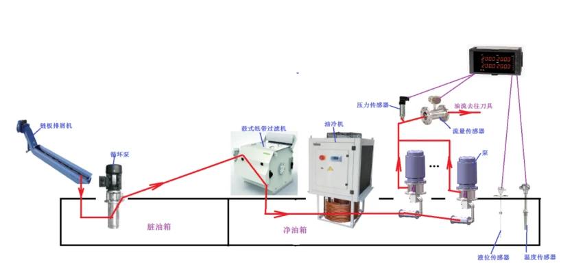
The cooling system comprises a coolant pump, chip conveyor, oil cooler, filtration unit, and reservoir, delivering an adequate flow of cutting fluid for deep-hole operations. The above-ground tank is fully welded from high-quality steel plate. The chip conveyor removes swarf and performs primary oil-chip separation. The oil cooler maintains fluid temperature within a preset range-automatically activating when the temperature exceeds the upper limit and ceasing when it falls below the lower threshold. The filtration unit employs paper-tape filtration with an automatic paper-feeding function to enhance oil cleanliness. Pressure, level, temperature, and flow rate are digitally displayed at the control station.
Machine mainly Parameters :
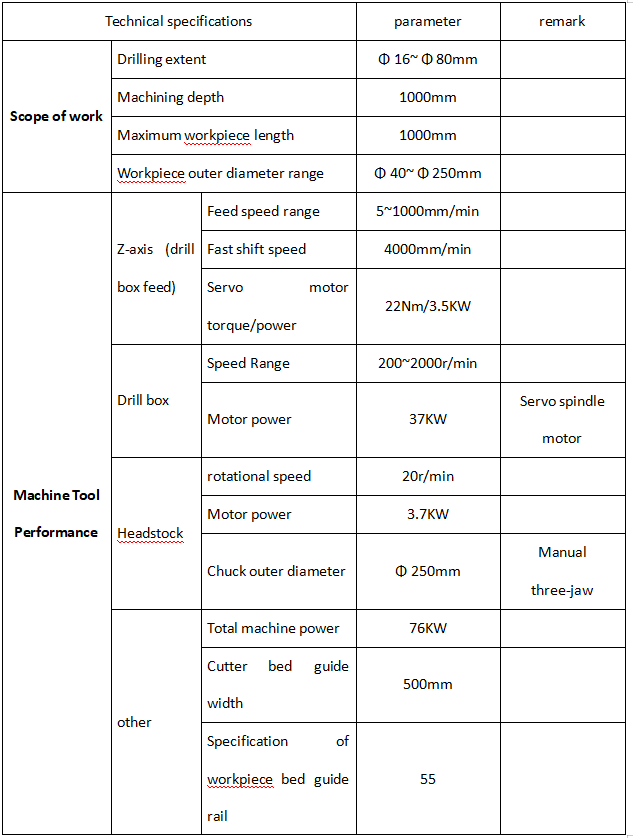
Machine configuration List

Contact us:
Bonnie
Email:info@dzguanlu.com
WhatsApp:+86 15153489983
Hot Tags: zsk2108 cnc deep hole drilling machine, China, suppliers, manufacturers, factory, customized, price, cheap, company, cost, for sale
You Might Also Like


